background image

4

bromic.com/heat

IMPORTANT NOTES & WARNINGS 

        WARNING

• 

IMPORTANT - Installation MUST be carried out by a licensed 
electrical contractor.

• 

Heater must be installed by 2 persons.

• 

Improper installation, adjustment, or alteration and failure 
to follow the warnings and instructions in this manual could 
result in severe personal injury, death or property damage.

• 

The manufacturer is not responsible for any damage 
resulting from improper use. The manufacturer emphasises 
that this appliance should be used in a responsible manner 
and that all procedures, warnings, and safety instructions 
contained in this booklet should be followed strictly.

• 

The installer is to ensure that the requirements of the local 

authority, local electrical installation code, municipal building 
codes, and any other relevant statutory regulations are 
carried out.

• 

Do not use or store flammable materials near this appliance.

• 

This installation, operation and service manual should not be 
removed from the site of installation. Installer should leave 
manual with the customer for future reference.

• 

A minimum safety distance of 3.3 feet should always be left 
in front of the Heater Head.

• 

The Heater head must be installed at least 8.0 feet above 

the floor.

• 

The Heater must not be located immediately below or 
in front of an electrical socket outlet. Heat radiated from 
the appliance may damage the electricity outlet or plug if 
placed incorrectly.

• 

Any guard or other protective device removed for servicing 
(conducted by a licensed electrical contractor) must be 

fitted in place before operating the heater.

• 

This appliance can be used by children aged from 12 years 
and above and persons with reduced physical, sensory or 
mental capabilities or lack of experience and knowledge if 
they are supervised.

• 

Children shall not play with the appliance.

• 

Cleaning and user maintenance shall not be made by 
children without supervision.

• 

Children of less than 12 years should be kept away unless 
continuously supervised.

• 

Some parts of this product can become very hot and cause 
burns. Particular attention has to be given where children 
and vulnerable people are present.

• 

Keep packaging materials out of reach of children.

• 

Do not spray aerosols or flammable materials in the 

vicinity of this appliance while it is in operation or whilst 
heater surface is hot.

• 

Installation and repair

 must be carried out by a qualified 

and licensed electrical contractor only. The heater should 
be inspected before use and at least annually serviced 

and inspected by a qualified and licenced service 

technician.

• 

The Heater Head has no serviceable parts. For the Poles, 
please refer to the Maintenance and Servicing section for 
more details regarding troubleshooting and replacement 
parts.

• 

The LED contained in this luminaire is non-replaceable 
and must not be removed. 

• 

Do not perform maintenance until heater has been 
turned off, power disconnected, and heater temperature 
has cooled to room temperature.

• 

Certain materials or items, when stored under or near the 
appliance, will be subjected to radiant heat and could be 
discoloured or seriously damaged. Combustible materials 

e.g. floors, furniture, fixtures and plants must be kept a 

minimum of 3.3 feet from the front of the heater head.

• 

Be sure the heater is not facing the ceiling or flammable 

or combustible substances/ materials.

• 

This radiant heater is NOT intended to be installed on or 
in vehicles and/or boats.

• 

Do not attempt to alter the unit in any manner.

• 

Remove all transit protection & packaging before use.

• 

Do not paint any surface of the heater.

• 

Check for damage to the appliance regularly. The heater 
must not be used if the glass panel or any other part of 
the heater is damaged. If damage to the appliance is 
suspected, discontinue use immediately and contact the 

supplier or a qualified technician.

• 

After unpacking, make sure the appliance shows no signs 
of visible damage or tampering. If the appliance appears 
damaged, contact the place of purchase for assistance.

• 

This appliance must only be used on a 220-240V AC 
single-phase power supply.

• 

Do not touch the heating surface at any time, even when 
the heater is turned off and has cooled down.

• 

Do not touch the heater with wet hands at any time.

• 

At the end of this product’s useful life, it must not be 
disposed of as domestic waste, but must be taken to 
a collection centre for waste electrical and electronic 

equipment. It is the user’s responsibility to dispose of this 

appliance through the appropriate channels at the end 
of its useful life. Failure to do so may incur the penalties 
established by local laws governing waste disposal. 

Proper differential collection, and the subsequent 

recycling, processing and environmentally compatible 

disposal of waste equipment avoids unnecessary damage 

to the environment and possible related health risks, 
and also promotes recycling of the materials used in the 
appliance. For further information on waste collection 
and disposal; contact your local waste disposal service or 
the place of purchase.

• 

In case of direct connection to a supply line, a bipolar 
circuit breaker with contact opening distance of at 

least 1/8 inch must be fitted upstream from the supply 

line. Contact an authorised service technician if you 
are unsure if you have a circuit breaker installed on the 
premises.

!

Summary of Contents for BH0920001

Page 1: ... REFERENCE Cancer and Reproductive Harm www P65Warnings ca gov Cancer et Troubles de l appareil reproducteur www P65Warnings ca gov Cancer y Daño Reproductivo www P65Warnings ca gov AVERTISSEMENT PROP 65 POUR LES RESIDENTS DE LACALIFORNIE PROP 65 WARNING FOR CALIFORNI A RESIDENTS AVERTISSEMENT PROP 65 PARA LOS RESIDENTES DE CALIFORNI A ...

Page 2: ... Read all instructions before installing servicing or using this heater For the ceiling wall mounted heater installation must comply with NEC and CEC code and local building code This heater is hot when in use To avoid burns do not let bare skin touch the hot surfaces Keep combustible materials such as furniture pillows bedding papers clothes and curtains at least 3 3 feet from the heater head in ...

Page 3: ... 22 BOX CONTENTS 15 16 WARNING 17 INSTRUCTIONS FOR WALL MOUNTED OPTION 18 22 ELECTRICAL INSTALLATION PENDANT HEATER CONTROLS 23 25 PENDANT HEATER CONTROL WIRING DIAGRAM 26 27 FOR INSTALLATION USING BROMIC ECLIPSE PENDANT CONTROL 26 FOR INSTALLATION NOT USING BROMIC ECLIPSE PENDANT CONTROL 27 OPERATION INSTRUCTIONS 28 30 REMOTE CONTROL FUNCTIONS 28 TURNING THE APPLIANCE ON 28 TURNING THE APPLIANCE ...

Page 4: ...chnician The Heater Head has no serviceable parts For the Poles please refer to the Maintenance and Servicing section for more details regarding troubleshooting and replacement parts The LED contained in this luminaire is non replaceable and must not be removed Do not perform maintenance until heater has been turned off power disconnected and heater temperature has cooled to room temperature Certa...

Page 5: ...m shipping container to prevent from injury when lifting heavy parts Maximum safe lifting 35 lbs per person Do not install heater to an unsecured structure Mounting surface integrity shall be determined suitable by the installer based on weight type of mounting option chosen Do not lean on heater or rest any objects leaning up against heater including the arm Do not hang any foreign items off any ...

Page 6: ...roval Electrical SGS 801126 US CAN Radio FCC ID P59TVEVO916S US Radio IC 11242A TVEVO916S CAN EMC SGS GZEM201101691501 US GZEM201101691601 CAN The Eclipse Smart HeatTM Electric is designed to provide efficient space heating for commercial and residential applications The Eclipse Smart HeatTM Electric heaters have electrical approval in Australia New Zealand USA Canada Europe UK and are rated to IP...

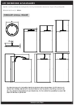
Page 7: ...g material with a low heat tolerance such as plastic vinyl siding canvas tri ply etc may subject to degradation at lower temperature It is the installer s responsibility to assure that adjacent materials are protected Heaters must be installed according to the minimum installation clearances shown in these diagrams Dimensions shown in Inches PENDANT WALL MOUNT ...

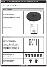
Page 8: ...re assembled 2 x Dome Head Screws M4 Length 6mm Pendant Pole Assembly one of the following styles Twin Straight Ceiling Mount Pole 24 Curved Ceiling Mount Pole 24 Straight Ceiling Mount Pole 8 Straight Ceiling Mount Pole 24 Straight Ceiling Mount Pole 48 Instruction Manual This Document 6 x Dome Head Screws M4 Length 6mm 2 x Dome Head Screws M4 Length 10mm ...

Page 9: ...m maintenance or carry out installation or assembly procedure while electrical power is switched on Wait 2 hours after switching off the heater before handling to prevent touching hot surfaces For longest product life and to maintain product appearance position heater under cover and protect from rain and weather The appliance must be installed such that the heater head is level with the ground Th...

Page 10: ...or the mounting surface Ensure the bracket is firmly secured to appropriate supports not only to ceiling panels with fasteners in 4 opposing holes before proceeding 1 Unpack all items from shipping cartons and place items on a non abrasive surface Instructions for Single Pole options including Curved Ceiling Mount Pole 24 Straight Ceiling Mount Pole 8 Straight Ceiling Mount Pole 24 Straight Ceilin...

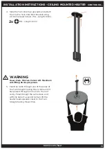
Page 11: ... M4 Length 6mm on both sides and tighten all four screws to lock heater in place 5 Feed the cable through the Ceiling Mount Pole until it has passed through and out into the roof cavity Feed through the cable slack and with the help of a second person lift the Heater Head upwards closer to the Ceiling Mount Pole INSTALLATION INSTRUCTIONS CEILING MOUNTED HEATER CONTINUED 2x M4 Length 6mm Heavy Item...

Page 12: ...red to appropriate supports not only to ceiling panels with fasteners in 4 opposing holes before proceeding 3 Place the Twin Pole Cap loosely onto the Twin Straight Ceiling Mount Pole as shown below and attach the Twin Straight Ceiling Mount Pole to the Twin Pole Roof Bracket using the 4 X Dome Head Screws M4 Length 6mm INSTALLATION INSTRUCTIONS CEILING MOUNTED HEATER CONTINUED 4x M4 Length 6mm IM...

Page 13: ...the Twin Straight Ceiling Mount Pole until it has passed through and out into the roof cavity Feed through the cable slack and with the help of a second person lift the heater head upwards closer to the Twin Straight Ceiling Mount Pole INSTALLATION INSTRUCTIONS CEILING MOUNTED HEATER CONTINUED 2x M4 Length 6mm Heavy Item Min Two Person Lift Maximum safe lifting 35 lbs per person WARNING ...

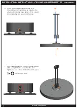
Page 14: ...es and tighten all four screws to lock heater in place INSTALLATION INSTRUCTIONS CEILING MOUNTED HEATER CONTINUED 2x M4 Length 6mm 6 Insert the Heater Bracket into the Twin Straight Ceiling Mount Pole by hooking the attached 2X Dome Head Screws M4 Length 6mm into the slot feature in the Pole ...

Page 15: ...Mounted Heater Box 1 Contents Box 2 Contents Eclipse Head Assembly Including pre assembled 2 x Dome Head Screws M4 Length 6mm Wall Mount Pole Instruction Manual This Document Wall Bracket Wall Bracket Cover INSTALLATION INSTRUCTIONS WALL MOUNTED HEATER ...

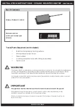
Page 16: ...ws M4 Length 6mm 1 x M20x1 5 Blanking Plug Tools Parts Required not Included Bolts for fastening to Wall surface Phillips Head Screw Driver Allen Key Step Ladder 2 strong people to help with lifting Spirit Level Box 3 Contents Eclipse Pendant Control INSTALLATION INSTRUCTIONS WALL MOUNTED HEATER CONTINUED Remote control with wall holder and screws ...

Page 17: ...s after switching off the heater before handling For longest product life and to maintain product appearance position heater under cover and protect from rain and weather The appliance must be installed such that the heater head is level with the ground The appliance must be mouted on a solid surface and it is the responsibility of the installer to assess the suitibility of the mounting surface Mi...

Page 18: ... Mount the Wall Bracket on the wall in the desired location using appropriately sized and type bolts not included for the mounting surface Ensure the bracket is firmly secured with fasteners in the 6 holes before proceeding IMPORTANT Fasteners must be chosen by installer to suit mounting structure Installer is responsible for chosing fasteners appropriate to the loading of the product Calculated t...

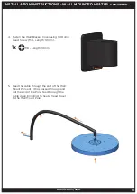
Page 19: ...Length 10mm 5 Feed the cable through the end of the Wall Mount Pole until it has passed through and out the end of the Pole Feed through the cable slack bringing the heater head closer to the Wall Mount Pole INSTALLATION INSTRUCTIONS WALL MOUNTED HEATER CONTINUED 1x M4 Length 10mm ...

Page 20: ...eature in the Pole NOTE Heater head should be positioned so that the bromic logo on the glass is at the front of the heater furtherst away from the wall 7 Fully fasten additional 2 X Dome Head Screws M4 Length 6mm on both sides and tighten all four screws to lock heater in place INSTALLATION INSTRUCTIONS WALL MOUNTED HEATER CONTINUED 2x M4 Length 6mm ...

Page 21: ...ty or alternatively the cable can be fed out of the optional Cable Slot in the underside of the Wall Bracket In this instance attach an M20 metal cable gland not supplied into the same hole from the outside of the bracket INSTALLATION INSTRUCTIONS WALL MOUNTED HEATER CONTINUED 1x M8 Length 15mm Option 1 Cable into Wall Cavity Option 2 Cable out of underside Heavy Item Min Two Person Lift Maximum s...

Page 22: ...Dome Head Screw M6 Length 10mm The Wall Bracket angle can be adjusted up to 45 from the wall on each side 11 If the cable has been routed into the wall cavity Insert the Cable plug into the optional cable slot INSTALLATION INSTRUCTIONS WALL MOUNTED HEATER CONTINUED 2x M6 Length 10mm ...

Page 23: ...r the heaters voltage and wattage The fixed wiring must be positioned away from protected from the enclosure of the heater Make all connections in accordance with local electrical code regulations For outdoor installation all connections must be made in accordance with local electrical code regulations for outdoor wiring Only use wiring components approved for outdoor use with minimum IP54 rating ...

Page 24: ...m heat ELECTRICAL INSTALLATION PENDANT HEATERS CONTROL 1 Open cover to the Pendant Control Box by removing 6x Oval head screws 4 40 Length 1 2 from the cover 2 Wire the power supply not included as per the wiring diagram The Live Neutral and Ground supply wires connect to their corresponding L N and Ground WAGO 3 way quick connectors The Power source MUST NOT be live when installing the Eclipse Co...

Page 25: ...riately sized and type screws not included for the mounting surface Ensure the Pendant Heater Control is firmly secured with fasteners in the 4 holes before proceeding 4 Wire the 6 Core Cable from the Eclipse Control Box to the Corresponding coloured wires on the 6 core cable from the Eclipse Heater Head according to local Electrical Code regulations Ensure connection is adequately protected from ...

Page 26: ...an 86 F ambient away from other heat sources and separation clearances maintained Wiring must be completed according to local electrical code 24VDC lighting circuit is to be separated inside the junction box from 220 240VAC circuits Electrical installation must ensure earth continuity is checked FOR INSTALLATION USING BROMIC ECLIPSE PENDANT CONTROL Bromic Eclipse Pendant Control supplied separatel...

Page 27: ... BY LICENSED AUTHORIZED TECHNICIAN APPLIANCE MANUAL MUST BE READ BEFORE INSTALLING OR SERVICING THIS PRODUCT To control elements independantly L1 66 element L2 33 element need independant 220 240V power supplies Power supply 220 240V a c Minimum Circuit Ampacity 17A Provided by installer Power supply to suit rated input of transformer Provided by installer LED Transformer Output 24V DC Power Ratin...

Page 28: ...have lowered to the desired level 4 To Brighten lights Press Hold 100 DIM until the lights have increased to the desired level NOTE It is normal to observe a small dim spot on the LED at the location where the LED joins together TURNING THE APPLIANCE OFF 1 Using the Remote Control press on the desired Heater setting Heater OFF Heater off 2 Using the Remote Control select the desired Light setting ...

Page 29: ... way PAIRING REMOTE CONTROL TO HEATER PCB TOP 4 BUTTONS OF REMOTE WARNING MUST ONLY BE SERVICED BY LICENSED AUTHORIZED TECHNICIAN 1 Open cover to the Pendant Control Box by removing 6x Oval head screws 4 40 Length 1 2 from the cover 2 Switch the power supply to the Eclipse Pendant Control ON 3 With the Eclipse Pendant Control powered ON PRESS HOLD the middle MEM button on the large heater control ...

Page 30: ...X SHORT PRESS followed by 1X PRESS HOLD While the LED PCB button is held down SHORT PRESS the Lights 100 button on the remote control 5 The LED on the Heater head will flash 3 times to indicate the remote is paired 6 Refit cover to the box ensuring the 6 X M3 O Rings are present on the 6x Oval head screws 4 40 Length 1 2 Heater 100 Heater output at full 100 Heater 66 Heater output at 66 of total H...

Page 31: ...ation or assembly procedure while electrical power is switched on ELECTRICAL SHOCK HAZARD Serious injury or death may occur Disconnect from electrical supply before installing or servicing this heater Read and follow installation clearance requirements outlined in this manual The appliance MUST be connected to a properly grounded electrical source Isolate mains before installing Use only with a pr...

Page 32: ...5 Remote too far 6 Radio interference 7 Remote not paired or faulty control 1 Choose lighting setting using remote 50 or 100 DIM 2 Connect to 220 240V power supply 3 Check connection to power supply 4 Change remote batteries 5 Move remote closer to heater 6 Move remote closer to heater disable other radio emitting devices 7 Pair remote to LED PCB Not enough Light 1 Incorrect lighting setting chose...

Reviews: