MASS-STREAM
TM
Manual Flow Switch D-6300/FS
9.17.114A – edition: 2017-07
Page 11 of 36
There are no regular maintenance checks required for the instrument’s operation. It has to
be ensured that a possible mounted inline filter is checked and cleaned on a regular
basis. We recommend having the calibration checked every 24 months by the supplier or
an authorized service partner.
2.4 Output Variants of the Switch-Point
The digital D-6300/FS Flow Switches provide 3 different setting options in 2 different
switching variants. The required variant for the referring instrument configuration needs to
be determined with the Flow Switch order.
The output voltage on Pin 5 is identical to the supply voltage (+15…24 Vdc) for the
operation of the Flow Switch.
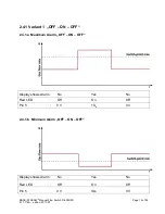
Applying variant 1 „OFF – ON – OFF“ and according to one of the 3 selectable switching
variants (see 2.4.1.a…2.4.1.c) the Flow Switch forwards a voltage to Pin 5 of the 8-pole
instrument connector, when the switch-point (for example minimum alarm) has been
activated.
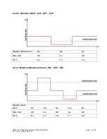
Applying variant 2 „ON – OFF – ON“ and according to one of the 3 selectable switching
variants (see 2.4.2.a…2.4.2.c) the Flow Switch interrupts the voltage to Pin 5 of the 8-pole
instrument connector, when the switch-point (for example maximum alarm) has been
activated.
If needed, the individually adjustable switch-point can be adapted to the required
operation conditions at any time.
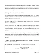
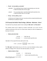
The minimum alarm and maximum alarm of the instrument requires values in [%]!
𝑠𝑠𝑠𝑠𝑠𝑠𝑠𝑠𝑠𝑠ℎ − 𝑝𝑝𝑝𝑝𝑠𝑠𝑝𝑝𝑠𝑠
[%] =
𝑠𝑠𝑠𝑠𝑠𝑠𝑠𝑠𝑠𝑠ℎ − 𝑝𝑝𝑝𝑝𝑠𝑠𝑝𝑝𝑠𝑠
𝑓𝑓𝑓𝑓𝑝𝑝𝑠𝑠
𝑟𝑟𝑟𝑟𝑠𝑠𝑟𝑟
100%
𝑓𝑓𝑓𝑓𝑝𝑝𝑠𝑠
𝑟𝑟𝑟𝑟𝑠𝑠𝑟𝑟
∙
100%


