Bronkhorst®
Instruction Manual EL-FLOW® Prestige
9.17.084N
24
3.5.1
Cabling
This section shows cabling examples of some
EL-FLOW® Prestige
instruments in an RS485 fieldbus system. Note that many
other fieldbus configurations are possible, contact your local sales representative for more information. Please check the
total power consumption of your instruments and do not exceed the maximum power of the power supply.
FLOW-BUS setup
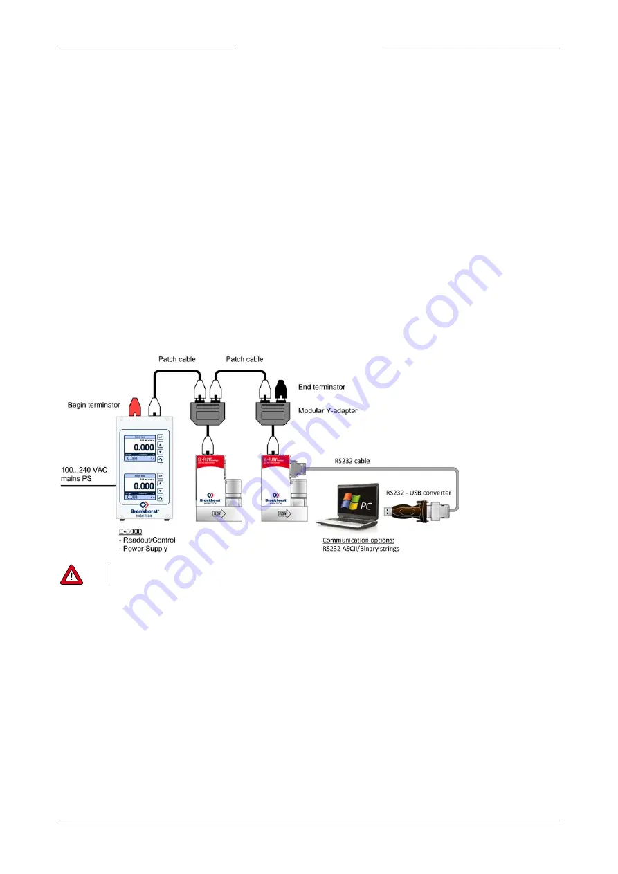
In the example below an E-8000 power supply/readout control unit with FLOW-BUS is connected to two
EL-FLOW® Prestige
instruments via the RJ-45 top-connector FLOW-BUS interface. In this example one instrument serves as a local host for RS232
communication with a Windows computer through the 9-pin D-sub connector on the side of the instrument. All other
instruments on the FLOW-BUS network are also accessible via the local host. It is even possible to use multiple local host
RS232/FLOW-BUS interfaces simultaneously.
The following components are used in this example:
·
2x EL-FLOW® Prestige
·
2x modular Y adapter cable (art. no. 7.03.241)
·
2x RJ-45 patch cable (art.no 7.03.238)
·
RJ-45 begin terminator (art. no. 7.03.297)
·
RJ-45 end terminator (art. no. 7.03.298)
·
E-8000 power supply, readout and control module
·
RS232 cable (art.no. 7.03.367)
·
RS232-USB converter (art no. 9.09.122)
·
Windows computer
Power the instruments in a FLOW-BUS local-host system by hooking-up the power supply directly on the FLOW-BUS line
and not by powering instruments through the 9-pin D-sub connector.


