Bronkhorst®
Instruction Manual FLEXI-FLOW™ Compact
9.17.158A
11
2
Installation
2.1
Product specifications
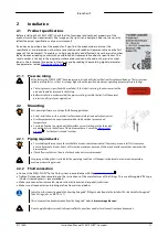
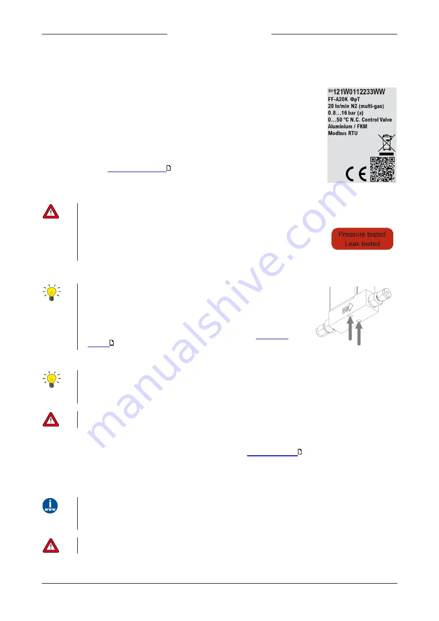
Before installing the FLEXI-FLOW™, check that the functional and technical properties of the
product match your requirements (the image on the right is an example; it does not necessarily
reflect the actual specifications of your instrument).
If you have a question about the product or if you find the product does not meet the
specifications as ordered, do not hesitate to contact your Bronkhorst representative (see the first
pages of this document). To enable us to help you quickly and effectively, have the serial number
ready whenever seeking contact with your Bronkhorst representative about a specific item. The
serial number is the key to the original purchase order and can be found on the serial number
label, in the instrument properties in FlowSuite and by reading the according digital parameter
(see parameter section
).
2.1.1
Pressure rating
At the factory the FLEXI-FLOW™ has been pressure tested and tested with helium for outboard leakage. The test pressure
includes a safety factor, so that it is always higher than the specified maximum operating pressure (pressure rating).
·
The test pressure is specified with a red label; if this label is missing, the device must not be
used and should be returned to the factory.
·
Before installation, make sure that the pressure rating is within the limits of the normal
process conditions of your application.
2.2
Mounting
For optimal performance, observe the following guidelines:
·
Avoid installation in close proximity of mechanical vibration and/or heat sources.
·
Use the equipment in an environment with a stable ambient pressure and
temperature.
·
For stable fixation to a rigid and stable surface or construction, use the threaded
mounting holes in the bottom of the instrument base. Consult the
for the exact size and locations.
2.2.1
Piping requirements
·
For reliable performance, make sure the fluid stream is uncontaminated. If necessary, use an inlet filter to ensure a
particle free media stream. Select a filter with a maximum pore size of 20 µm and a surface area that minimizes the
pressure drop.
·
If back flow could occur, the use of a check valve is also recommended.
Use piping or tubing that is suitable for the operating conditions of the application (media, maximum temperature,
maximum operating pressure).
2.2.2
Fluid connection
·
Connect the FLEXI-FLOW™ to the fluid system in accordance with the
.
·
Tighten fluid connections according to the instructions of the manufacturer of the fittings. The use of Swagelok® RS-type
stainless steel adapters is recommended.
·
Make sure connector sizes match; do not mix metric (mm) and imperial (inch) sizes.
·
Make sure all connectors and tubing are free from dirt and debris.
Instructions for connecting and disconnecting Swagelok® fittings can be found in the Installer's Pocket Guide for Swagelok®
Tube Fittings (doc. no MS-13-151)
This document can be downloaded from the Swagelok® website (
Do not apply fluid pressure until all required fluid connections and electrical connections have been made.
32
9
7


