


Bronkhorst®
Instruction Manual IQ+FLOW® Series Digital Mass Flow / Pressure Controllers for Gases
9.17.045V
14
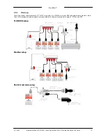
3.3
Manual interface: micro-switch, LEDs and rotary switches
In this section the manual instrument interfaces are described:
·
Micro-switch
·
Indication LEDs
·
Rotary switch
3.3.1
Micro-switch operation (single-channel versions only)
By means of manual operation of the micro push-button switch some important actions for the instrument can be selected
or started. These options are available in both analog and digital operation mode.
These functions are:
·
Reset alarm
·
Reset instrument (firmware program reset)
·
Auto-zeroing
·
Restore factory settings (in case of accidently changing of the settings)
Using digital RS232 or RS485 operation it is also possible to set:
·
Bus-address (only required for RS485)
·
Baudrate
·
Change control mode
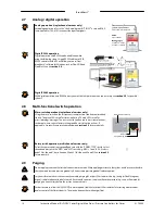
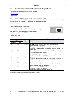
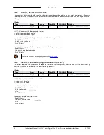
Multi-functional switch
Status LED
Error/Warning LED
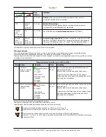
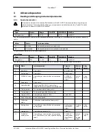
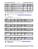
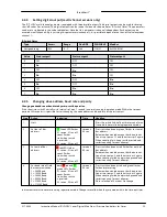
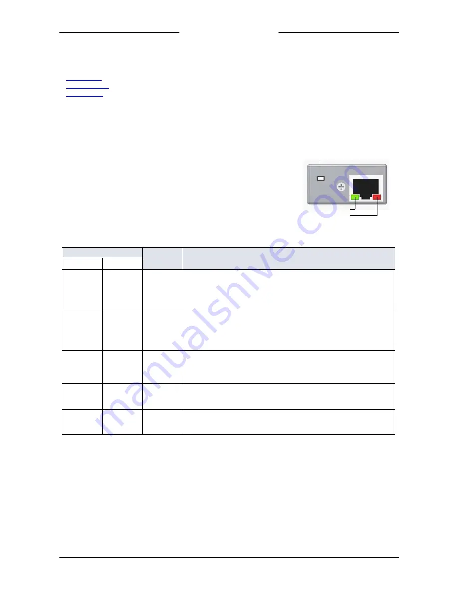
The tables below describe the micro-switch functions that can be started in normal operation mode and during power-up:
LEDs
Time
Pushed
Indication
Green
Red
Off
Off
0 – 1 sec.
No action
. Pressing a switch shortly by accident will not start any
unwanted reaction of instrument.
Pressing the switch 3x briefly with intervals of max. 1 sec. forces the
instrument to indicate its bus-address and baud rate. Check
section 3.5
for
more details.
Off
Off
1 – 4 sec.
In case of min/max alarm or counter batch reached:
Reset alarm
(only if
reset by keyboard has been enabled)
For FLOW-BUS only: if the node address is occupied, this function will
install a free node-address
on FLOW-BUS.
Off
On
4 – 8 sec.
Reset instrument
Instrument program will be restarted and all warning and error messages
will be cleared. During start-up the instrument will perform a (new) self-
test.
On
Off
8 – 12 sec.
Auto-zero
Instrument will be re-adjusted for measurement of zero-flow (not for
pressure meter/controller). See
section 2.10
.
On
On
12 – 16 sec.
Prepare instrument for
FLASH mode
for firmware update.
Instrument shuts down and both LEDs turn off.
At next power-up instrument will be active again.
LED indications using micro-switch at normal operation mode of an instrument


