background image

Bronkhorst®

Instruction Manual IQ+FLOW® Series Digital Mass Flow / Pressure Controllers for Gases

9.17.045V

15

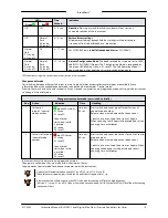
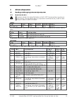
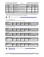
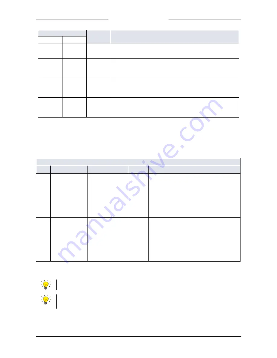
LEDs

Time
Pushed

Indication

Green 

Red 

Off

Off

0 – 4 sec.

No action

. Pressing a switch shortly by accident will not start any

unwanted reaction of the instrument.

Off

Normal

flash

0,2 sec on,

0,2 sec off

4 – 8 sec.

Restore factory settings

All parameter settings (except field bus settings) will be restored to

situation of final test at Bronkhorst® production.

Normal

flash

0,2 sec on,

0,2 sec off

On

8 – 12 sec.

For FLOW-BUS only: 

install a free node-address

 on FLOW-BUS.

Normal

flash

0,2 sec on,

0,2 sec off

Normal

flash

0,2 sec on,

0,2 sec off

12 – 16 sec

Activate 'Configuration Mode'

. The baud rate and bus type are set to 38k4

and RS232 FLOW-BUS (Propar). The 'Configuration Mode' is recognized by

the green LED blinking 2 sec on, 0,1 sec off. The 'Configuration Mode' is

deactivated only after applying this micro-switch action again.

LED indications using micro-switch at power-up situation of an instrument

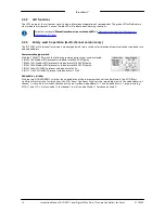
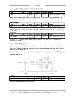
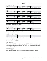
Change control mode

For switching between different functions in use of a digital meter or controller several modes are available. More

information about the available control modes can be found at parameter “Control mode”. 

Pressing the switch 4x briefly with intervals of max. 1 second in normal running/operation mode will trigger the instrument

to “change” its control mode.

Change current control mode (press switch 4x briefly)

Step

Action

Indication

Time

Handling

1

Set tens of

setpoint / control

mode number

 green LED flashes

0.1 sec on

0.1 sec off

Count-flashes

start when switch

is pressed:

0.5 sec on

0.5 sec off

time-out:

60 sec

Press switch and count green flashes for tens of

control mode number.

Release when wanted amount has been count.

Counts up to max. 2 and than starts at 0 again.

When counting fails, keep switch pressed and restart

counting for next attempt

2

Set units of setpoint

/ control mode

number

 red LED flashes

0.1 sec on

0.1 sec off

Count-flashes

start when switch

is pressed:

0.5 sec on

0.5 sec off

time-out:

60 sec

Press switch and count red flashes for units of control

mode number.

Release when wanted amount has been count.

Counts up to max. 9 and than starts at 0 again. When

counting failed, keep switch pressed and restart

counting for next attempt.

Instrument returns to normal running/operation mode. 

Changes are valid when they are made within the time-out times.

See parameter ‘Control mode’ for behavior at power-up of the instrument.

Value zero will be indicated by a period of 1 sec. off (0.5 sec. off + 0.5 sec. off).

When value zero is wanted, press switch shortly and release it again within 1 sec.

Before each action of flash-counting, the LED’s to be used for counting will flash in a high frequency.

(Pattern: 0.1 sec on, 0.1 sec off).  As soon as the switch is pressed-down, this LED (or both LED’s) will be off and the counting

sequence will start.

Summary of Contents for IQ+Flow series

Page 1: ...read this Instruction Manualcarefully beforeinstalling and operating theinstrument Notfollowing theguidelines could resultin personalinjury and ordamageto theequipment IQ FLOW series Digital Mass Flow Pressure Controllers for gases Instruction Manual ...

Page 2: ...r installation Helpful information Thisinformationwill facilitatetheuseoftheinstrument and or contributetoitsoptimal performance Additional infoavailableontheinternet or from your local Bronkhorst representative Receipt of equipment Check the outside package box for damage incurred during shipment If the box is damaged then the local carrier must be notified at once regarding his liability if so r...

Page 3: ...s This product is intended for use by qualified personnel who recognize shock hazards and are familiar with the safety precautions required to avoid possible injury Read the operating information carefully before using the product Before operating make sure the line cord is connected to a properly grounded power receptacle Inspect the connecting cables for cracks or breaks before each use The equi...

Page 4: ...Bronkhorst Instruction Manual IQ FLOW Series Digital Mass Flow Pressure Controllers for Gases 9 17 045V 4 ...

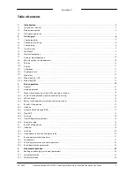
Page 5: ... 3 1 General 13 3 2 Analog operation 14 3 3 Manual interface micro switch LEDs and rotary switches 14 Micro switch operation single channel versions only 3 3 1 16 LED functions 3 3 2 16 Rotary switch operation multi channel versions only 3 3 3 17 3 4 Basic RS232 operation 17 Hook up 3 4 1 17 Dynamic Data Exchange DDE 3 4 2 17 FlowDDE 3 4 3 18 Software 3 4 4 18 FlowDDE parameter numbers 3 4 5 18 Ba...

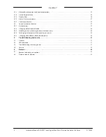
Page 6: ...27 4 2 Special instrument features 27 Auto zeroing 4 2 1 28 Changing default control mode 4 2 2 28 Disabling micro switch single channel versions only 4 2 3 29 Setting digital output multi channel versions only 4 2 4 29 Changing slave address baud rate and parity 4 2 5 31 Troubleshooting and service 5 31 5 1 General 31 5 2 LED indication 31 5 3 Troubleshooting summary general 32 5 4 Service 33 Ret...

Page 7: ...ailable with the same footprints to meet customer demands The IQF flow sensor is a fast response chip sensor with the main advantage of fast and reliable control response This is possible due to the MBC3 based pc board and the flow sensor which output signal very accurately corresponds with the real flow behavior Communication with the devices can be either in analog mode or digital over RS232 or ...

Page 8: ...ctively make sure to have the serial number ready whenever seeking contact with Bronkhorst about a specific item The serial number SN is the key to the original purchase order See section Service for contact information 2 2 Check pressure rating Bronkhorst instrumentsarepressuretestedtoat least 1 5 timesthespecifiedworkingprocess conditionsandoutboardleaktestedtoat least 2 10 9 mbar l sHelium Thet...

Page 9: ...nmust bemadefor eachnewadapter toensureleak tightnessand minimum deadvolume duetovariancesintheadapter dimensions Mounting downported instruments For downportedinstrumentsmakesurethat thesealsarepresent at thebottom that thesurfacesareundamagedandthat theyaredryandfreefrom dirt or dust 2 5 Leak check Checkthefluidic system for leaksbeforeapplyingpressure especiallywhenusinghazardousmedia e g toxic...

Page 10: ...beusedtostart several actions suchasauto zero restorefactorysettingsandbus initialisationactions if applicable Seespecific zero procedurebelowandsection 3 3 for moredetails Multi functional switch Status LED Error Warning LED Rotaryswitch operation multi channelversionsonly Select thecommunicationtypeandBaudratewiththe COMM TYPE switch Select thenodeaddresswiththe MSD and LSD switch e g MSD 1 andL...

Page 11: ...est point tozeroisaccepted Theprocedurewill takeapproximately10 seconds Whentheindicationisshowing0 signal andthegreenindicationLED isburningcontinuouslyagain thezeroing actionwassuccessful 2 11 Calibration Each IQ FLOW instrument is factory calibrated Bronkhorst certifies that all instruments meet the rated accuracy Calibration is performed using measurement standards traceable to the standards o...

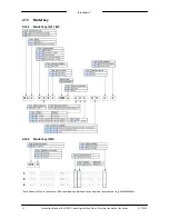
Page 12: ...FLOW Series Digital Mass Flow Pressure Controllers for Gases 9 17 045V 12 2 13 Model key 2 13 1 Model key IQF IQP 2 13 2 Model key IQM Each channel of an instrument will be provided an additional letter after the serial number e g M AA ...

Page 13: ...nnel Not supported FLOW BUS Propar protocol on 38400 or 115200 Baud select with rotary switch Modbus RTU protocol on 9600 19200 or 38400 Baud select with rotary switch 3 2 Analog operation Analog operation is only possible with single channel IQ FLOW instruments Multi channel instruments can only be operated digitally At analog operation the following signals are available Measured value analog ou...

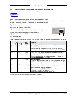
Page 14: ...ted in normal operation mode and during power up LEDs Time Pushed Indication Green Red Off Off 0 1 sec No action Pressing a switch shortly by accident will not start any unwanted reaction of instrument Pressing the switch 3x briefly with intervals of max 1 sec forces the instrument to indicate its bus address and baud rate Check section 3 5 for more details Off Off 1 4 sec In case of min max alarm...

Page 15: ...on mode will trigger the instrument to change its control mode Changecurrentcontrolmode pressswitch 4xbriefly Step Action Indication Time Handling 1 Set tens of setpoint control mode number green LED flashes 0 1 sec on 0 1 sec off Count flashes start when switch is pressed 0 5 sec on 0 5 sec off time out 60 sec Press switch and count green flashes for tens of control mode number Release when wante...

Page 16: ...nication typeswitch With the COMM TYPE switch the following communication types can be selected 0 RS485 9k6 Modbus RTU protocol with baud rate 9600 EVEN parity 1 RS485 19k2 Modbus RTU protocol with baud rate 19200 EVEN parity 2 RS485 38k4 Modbus RTU protocol with baud rate 38400 EVEN partiy 3 RS232 38k4 FLOW BUS protocol with baud rate 38400 4 RS232 115k2 FLOW BUS protocol with baud rate 115200 No...

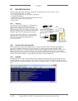
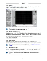
Page 17: ...oose end cable 7 03 419 typically for connection to PLC or microcontroller devices 3 4 2 Dynamic Data Exchange DDE RS232 communication can be used for operating the instrument using the Bronkhorst FlowDDE server application Dynamic Data Exchange DDE provides the user a basic level of interprocess communication between Windows applications FlowDDE is a DDE server application Together with a client ...

Page 18: ...nslated by FlowDDE to a channel number An instrument parameter can be changed by using the application name FlowDDE with only topic used for channel number C X item used for parameter number P Y 3 4 6 Baud rate setup Make sure that the instrument s baud rate corresponds with the baud rate of the application the instrument is communicating with For single channel instruments the selectable baud rat...

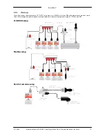
Page 19: ...9 17 045V 19 3 5 1 Hook up These illustrations show examples of IQ FLOW instruments in a RS485 bus system When the power consumption is more than 15W two separate power supplies are required due to the maximum power supply of 15 W for one PiPS FLOW BUS setup Modbus setup RS232 stand alone setup ...

Page 20: ...sprotocol Propar FLOW BUS ModbusRTU ModbusASCII Baud rate 9600 19200 38400 57600 115200 187500 400000 9600 19200 38400 56000 57600 115200 9600 19200 38400 56000 57600 115200 Nodeaddress 3 125 3 125 1 247 1 247 Parity None None None Even Odd None Even Odd In case the baud rate or node address of an IQ FLOW instrument needs to be changed this can be done with the micro switch or by changing the sett...

Page 21: ...and written RW The parameter is protected and can only be written when the Init Reset parameter is set to 64 See section 4 1 1 for more details Range Some parameters only accept values within a certain range x Minimum value of the range y Maximum value of the range FlowDDE Parameter number within FlowDDE Refer to section 3 4 for more information about FlowDDE FLOW BUS Within the FLOW BUS protocol ...

Page 22: ...pressure for the controller The signals have the same range as the measured value only the setpoint is limited between 0 and 100 0 32000 A floating point variable of the setpoint Fsetpoint is also available in the capacity and capacity unit for which the instrument has been set see section 4 3 6 3 Basic identification parameters User Tag Type Access Range FlowDDE FLOW BUS Modbus Unsigned char 16 R...

Page 23: ...5 12 1 4 0x0024 37 The Control mode is used to select different functions of the instrument The following modes are available Value Mode Instrumentaction Setpoint source Master source Slave factor 0 BUS RS232 Controlling RS232 RS485 1 Analog input Controlling Analog input 2 FLOW BUS slave Controlling as slave of other instrument on bus FLOW BUS slave factor 100 FLOW BUS Slave factor 3 Valve close ...

Page 24: ... 1 16 0x0030 49 The Fluid number is a pointer to the set of calbration parameters Each selectable fluid has its own set of calibration parameter values Parameter value 0 fluid 1 and parameter value 7 fluid 8 Up to eight fluids can be stored in an instrument Default value 0 fluid 1 Fluid Name Type Access Range FlowDDE FLOW BUS Modbus Unsigned char 10 RW 25 1 17 0x8188 0x818C 33161 33165 This parame...

Page 25: ... 0 ValveOutput Type Access Range FlowDDE FLOW BUS Modbus Unsigned long RW 0 16777215 55 114 1 0xF208 0xF209 61961 61962 This parameter is the signal coming out of the controller used for driving the valve 0 16777215 corresponds with approximately 0 60 mAdc 4 1 4 Controller parameters The controlling algorithm for the valve handled by the micro controller consists of several parameters which can be...

Page 26: ...nse 1 05 128 Kspeed NormalStep response Knormal Type Access Range FlowDDE FLOW BUS Modbus Unsigned char RW 0 255 72 114 5 0x0E45 3654 Controller response during normal control at setpoint step Value 128 is default and means no correction Otherwise controller speed will be adjusted as follows New response Old response 1 05 128 Knormal StableSituation controlresponse Kstable Type Access Range FlowDD...

Page 27: ...structionsDigital Instruments document no9 17 023 4 1 7 Counter parameters SeeOperationInstructionsDigital Instruments document no9 17 023 4 2 Special instrument features 4 2 1 Auto zeroing To start the auto zero procedure by digital operation two parameters should be written ControlMode Type Access Range FlowDDE FLOW BUS Modbus Unsigned char RW 0 255 12 1 4 0x0024 37 Calibration Mode Type Access ...

Page 28: ...og operation Read IOStatus Add 64 to the read value Write IOStatus Procedure for changing default analog operation to default digital operation Read IOStatus Subtract 64 from the read value Write IOStatus Control modecanalsobechangedbymeansofthemicro switch 4 2 3 Disabling micro switch single channel versions only It is possible to disable the micro switch on top of the instrument This can prevent...

Page 29: ...Press the switch 5x briefly with intervals of max 1 second in normal running operation mode 2 Set tens of bus address Green LED flashes 0 1 sec on 0 1 sec off count flashes start when switch is pressed 0 5 sec on 0 5 sec off timeout 60 sec Press switch and count green flashes for tens of bus address Release when wanted amount has been count Counts up to max 12 and than starts at 0 again When count...

Page 30: ...ument isavailablefor communicationonthenewlyselectedparameters Whenin doubt activatethe ConfigurationMode 38k4 andRS232 FLOW BUS ProPar usingthemicro switch Fieldbus2 selection Type Access Range FlowDDE FLOW BUS Modbus Unsigned char RW 0 3 308 124 8 0xFC40 64577 This parameter sets the fieldbus type Parameter value 0 FLOW BUS 1 Modbus RTU 2 Propar 3 Modbus ASCII Fieldbus2 address Type Access Range...

Page 31: ...ructionsDigital Instruments document no9 17 023 5 3 Troubleshooting summary general Symptom Possiblecause Action No output signal No power supply Check power supply and hook up Check cable connection and hook up Check status of LEDs see Operation Instructions Digital Instruments document no 9 17 023 Cable damaged or hooked up incorrectly Check and compare signals at both ends of cable PC board dam...

Page 32: ...duct For current information on Bronkhorst and service addresses please visit our website www bronkhorst com Do you have any questions about our products Our Sales Department will gladly assist you selecting the right product for your application Contact sales by e mail sales bronkhorst com For after sales questions our Customer Service Department is available with help and guidance To contact CSD...

Page 33: ...17 032 canbe downloadedfrom theService Support sectionoftheBronkhorst website www bronkhorst com Important Clearly note on top of the package the customs clearance number of Bronkhorst High Tech B V NL801989978B01 only if applicable otherwise contact your local Bronkhorst representative for local arrangements 6 2 Disposal end of lifetime Within the scope of the European Union manufacturers of elec...

Reviews: