9.17.093
2
SCOPE OF THIS GUIDE
mini CORI-FLOW™
instruments are highly accurate instruments for measuring and controlling the mass flow rate of liquids and/or
gases, independent of fluid properties. These smart Coriolis instruments offer multiple process values as input- or output
parameters. Many parameters can be read and/or changed using analog or digital interfaces. Output parameters are: mass flow,
density, temperature, totalized mass flow, alarms. Input parameters are: setpoint (desired mass flow rate for controllers), reset
alarm/counter.
This manual will help you start-up your
mini CORI-FLOW™
ML120
in only 10 steps and contains:
1.
Instrument functional properties
2.
Check safety properties
3.
Check piping
4.
Mount/install instrument
5.
Leak check
6.
Electrical connection
7.
Operation
8.
Multi-functional switch
9.
Purging
10.
Zeroing
mini CORI-FLOW™ ML120
instruments have modular instruction manuals consisting of:
- Instruction manual
mini CORI-FLOW™ ML120
(document nr. 9.17.097)
Info about e.g. : sensors, valves, liquid dosing systems, maintenance, tooling, calibration, Kv-value calculation, troubleshooting.
- Hookup diagram
mini CORI-FLOW™
and
CORI-FLOW™
(general)
(document nr. 9.16.132)
- FlowPlot Manual
(document nr. 9.17.030)
Depending on optional fieldbus interface:
Fieldbus/interface description
Manual
Hookup diagram
- RS232 Interface with FLOW-BUS protocol
9.17.027
9.16.132
- FLOW-BUS Interface
9.17.024
9.16.133
- PROFIBUS DP Interface
9.17.025
9.16.134
- DeviceNet™ Interface
9.17.026
9.16.135
- Modbus interface
9.17.035
9.16.136
- EtherCAT interface
9.17.063
9.16.137
- PROFINET
9.17.095
9.16.146
i
www
These documents can be downloaded from the website:
http://www.bronkhorst.com/qrcoriolis
or can be sent by e-mail on request.
Notes for temperature considerations
After having used the
mini CORI-FLOW™ ML120
the first time at low temperature tighten the fluid adapter screws again in
order to prevent any leakage! Please note: if you do not tighten, the leaking adapter / fitting can cause damage! After the
first shrinking and tightening of the screws, no further precaution is necessary.
Note:
The maximum allowed temperature in the housing of the
mini CORI-FLOW™ ML120
is 70 °C. To check this, the
internal temperature sensor can be used. Temperature can be readout digitally via FLOW-DDE/E-8000 (FlowDDE par. 142) or
BRIGHT (local readout/control module). Make sure the temperature value readout here (=actual temperature in housing)
will not exceed 70 °C.
STARTING-UP
1
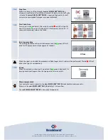
Check mini CORI-FLOW™ ML120 functional properties
Before installing your Mass Flow Meter/Controller it is important to
read the attached label and check:
·
Flow rate
·
Fluid to be measured
·
Up- and downstream pressures
·
Input/output signal
·
Temperature
·
Valve type
(if controller)


