© Bronkhorst High-Tech B.V.
3
2
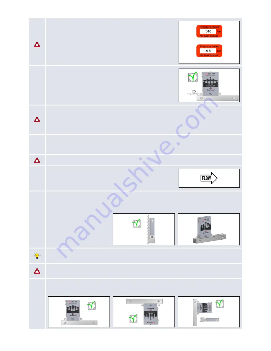
Check test-pressure
The tested pressure is stated on the instrument with a red-colored sticker.
Before installation, make sure that the test pressure is in accordance with
normal safety factors for your application. If there is no Pressure Testing
Sticker on the device or if the test pressure is incorrect, the instrument
should
not
be mounted in the process line and be returned to the factory.
NOTE! Tested pressure is higher than the (normal) operating pressure.
Mass Flow Meter
Mass Flow Controller
3
Check if system piping is clean
For reliable measurement always make sure the fluid stream is clean.
Use filters to assure a particle free liquid stream or a moisture- and
oil-free gas stream. Recommended pore size: 0,5...25 µm. If back flow
can occur, a downstream filter and a check valve are recommended too.
For high flow rates select a suitable filter size, to avoid too high
pressure drop or cavitation.
Warning!
During the manufacturing process, the instruments have been tested with water. Despite the fact that the
instruments have been purged thoroughly afterwards, we cannot guarantee that the delivered instruments are
absolutely free from water droplets. Bronkhorst strongly recommends performing an additional, adequate drying
procedure for those applications where remaining water particles may cause undesired reactions such as corrosion.
4.1
Mount/install instrument properly
Install the
mini CORI-FLOW™ ML120
Meter/Controller in the line and tighten the fittings according to the
instructions of the supplier of the fittings.
During operation avoid external vibrations and shocks.
4.2
Flow direction
Install the
mini CORI-FLOW™ ML120
in accordance with the direction of
the FLOW arrow. The arrow for flow direction is indicated on the
mini CORI-FLOW™ ML120
, between process fittings.
4.3
Base mounting
Mount the
mini CORI-FLOW™ ML120
instrument, with screws in the body, to a rigid, stiff base body or heavy mass,
such as a wall, heavy rig or stable construction. This is essential to achieve optimal accuracy with the
mini CORI-
FLOW™ ML120
instrument.
By default the
mini CORI-FLOW™ M12, M13, M14
and
ML-120
will be delivered on a special mounting block for
achieving optimal accuracy.This mounting block has a mass and stiffness precisely tuned for the specific model.
Removing the mounting block will cause inaccuracy unless the instrument is firmly mounted on a vibration free, stiff
and rugged surface. Mounting on plates of machine cabinets is not recommended.
4.4
Mounting position general
For gas and liquid
mini CORI-FLOW™ ML120
meters can be mounted in any position for a proper measurement.


