2-1
Installation
Installation
2-1 Receipt of Equipment
When the equipment is received, the outside packing case should be
checked for damage incurred during shipment. If the packing case is
damaged, the local carrier should be notified at once regarding his liability.
A report should be submitted to the Product Service Department, Brooks
Instrument, 407 West Vine Street, Hatfield, Pennsylvania 19440.
Remove the envelope containing the packing list. Carefully remove the
equipment from the packing case. Make sure spare parts are not
discarded with the packing material. Inspect for damaged or missing parts.
2-2 Recommended Storage Practice
If intermediate or long term storage is required for the equipment, as
supplied be Brooks Instrument, it is recommended that said equipment be
stored in accordance with the following:
a. Within the original shipping container.
b. Store in a sheltered area with the following conditions:
1. Ambient temperature 70°F (21°C) nominal, 90°F (32°C) maximum/
45°F (7°C) minimum
2. Relative humidity 45% nominal, 60% maximum 25% minimum.
Upon removal from storage, a visual inspection should be conducted to
verify the condition of the equipment is “as received". If the equipment has
been in storage for an excess of ten (10) months or under conditions in
excess of those recommended, all pressure boundary seals should be
replaced and the device subjected to a pneumatic pressure test in
accordance with applicable vessel codes.
2-3 General
A pressure controller system can be built in upstream or downstream
control configurations (refer to Figures 1-7 and 1-8). When the controller is
placed downstream (upstream pressure controller) of the pressure vessel,
the flow is usually determined by MFC(s) in the line upstream of the
vessel.
With the pressure controller upstream of the vessel (downstream pressure
controller), the most likely application is controlling a subatmospheric
pressure in the vessel. The inlet of the pressure controller can be at
atmospheric gas pressure or at vapor pressure of a liquid source. The flow
in this situation is usually determined by the characteristics of a vacuum
pump.
2-4 Gas Connections
Standard inlet and outlet connections on the Model 5866 and 1/4"
compression fittings. Optional VCO
TM
and VCR
TM
connections are available
upon request.
Section
2
Summary of Contents for 5866
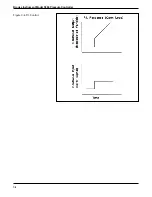
Page 20: ...3 3 Operation Figure 3 2 Proportional Control Figure 3 3 Integral Control ...
Page 21: ...Brooks Instrument Model 5866 Pressure Controller 3 4 Figure 3 4 P I Control ...
Page 23: ...Brooks Instrument Model 5866 Pressure Controller 4 2 ...
Page 32: ...5 9 Troubleshooting Figure 5 3 Valve Adjusting Spacer Locations ...
Page 34: ...5 11 Troubleshooting Figure 5 4 Valve Adjusting Spacer Locations Normally Open N O Valve ...
Page 43: ...Brooks Instrument Model 5866 Pressure Controller 6 6 ...
Page 45: ...Brooks Instrument Model 5866 Pressure Controller 7 2 Figure 7 1 Model 5866E Parts Drawing ...
Page 47: ...Brooks Instrument Model 5866 Pressure Controller 7 4 Figure 7 2 Model 5866M Parts Drawing ...
Page 48: ...7 5 Parts List Table 7 3 Model 5866M Parts List ...
Page 49: ...Brooks Instrument Model 5866 Pressure Controller 7 6 ...
Page 65: ......


