Polycold Cryochiller
Interfacing
Installation and Operation Manual
Gauge Relay (J4)
Brooks Automation
214072 Revision B
5-3
Gauge Relay (J4)
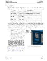
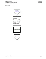
The Gauge Relay connection provides external control to place each refrigerant circuit into Cool Mode.
When the refrigerant circuit is in Standby mode and the Gauge Relay is enabled and the appropriate
Gauge Relay contact pair is provided a 24V AC/DC (-25%/+17%) 10MA input voltage across a Gauge
Relay pin pair, the selected refrigerant circuit goes into the current default Cool mode.
Example: A Granville-Phillips (G-P) Mini-Convectron
®
Gauge is used to control circuit 1. This gauge
has a pair of Process Setpoint Relay contacts that close when the gauge detects the setpoint pressure.
•
One side of the relay contacts on the
gauge is connected to a 24V power
source.
•
The other side of the relay contacts on
the gauge is connected to either pin 1
or pin 2 of the Polycold Cryochiller
Gauge Relay input.
•
Common for the 24V power source is
connected to the remaining pin 2 or pin
1 of the Polycold Cryochiller Gauge
Relay input.
When the G-P gauge detects that the process
has reached the programmed set point vac-
uum level, the G-P gauge contacts close and
the 24V is applied across Gauge Relay input
pins 1 and 2. The Polycold Cryochiller
responds by setting refrigerant circuit 1 to the
current default Cool mode.
See Gauge Relay Kit in
for the kit part number.
See
External Vacuum Control on page 8-4
.
Item Description
J4 Port
4-pin Connector (female pins)
Cable Connector
4-pin Cable Connector (male pins) (Amp CPC-11 - 206429-1)
Cable Terminal Pins
(4) crimp-style male pins for 16 to 18AWG wire size.
Cable Size
20 - 24 AWG
Input
Non-polar fully isolated 24VAC or 24VDC input signals
Circuit 1 Control
Pins 1 and 2
Circuit 2 Control
Pins 3 and 4 (Only on units with full Circuit 2 control)
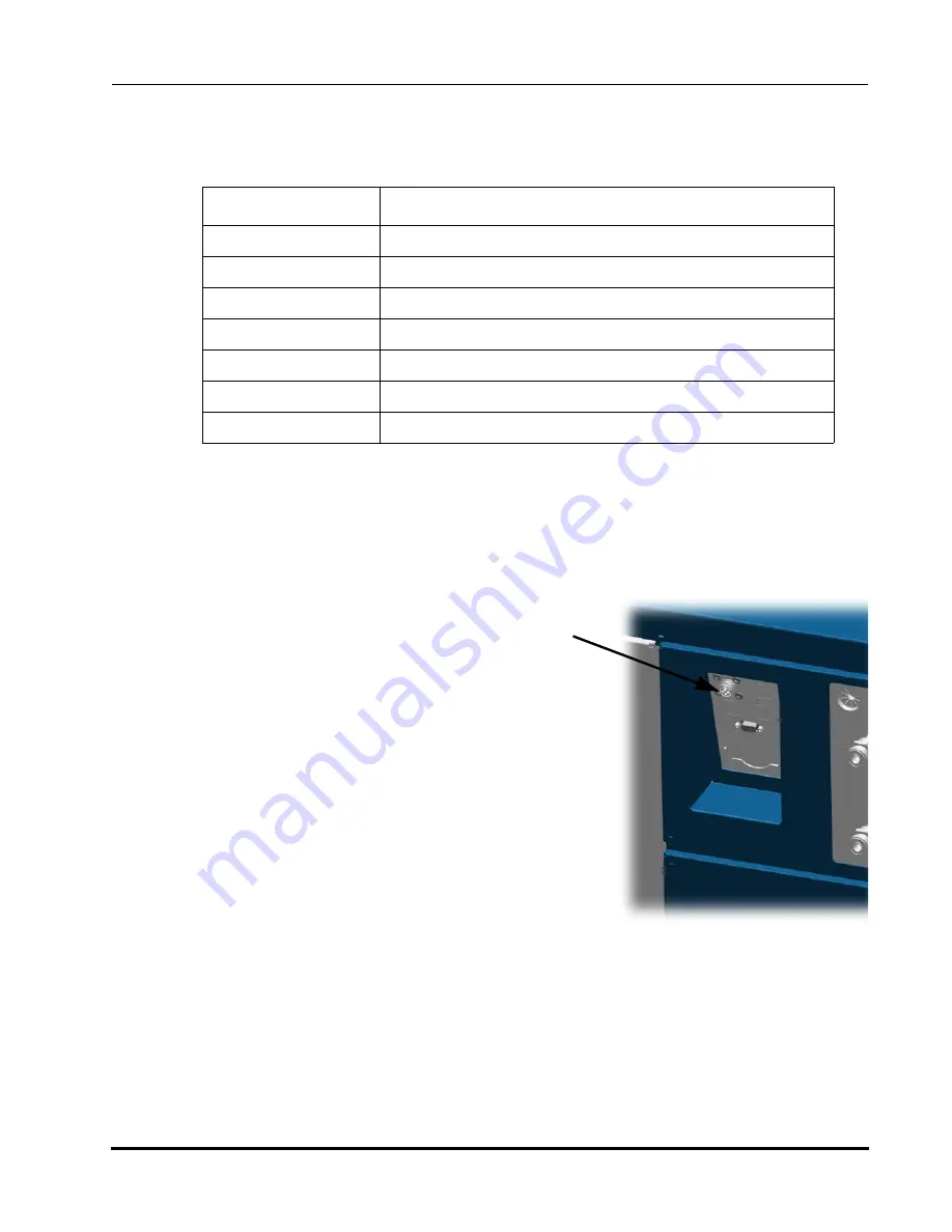
Figure 5-3: Gauge Relay Connection
Gauge
Relay
Connection

