background image

P

H

G

G

A

Step 4

A x 3

G x 18

H x 6

P x 3

4.1

 Align one part of the back panel to the the structure 

making sure the holes are facing upward and gently 

slide along the grooves down to the base. Insert a 

dowel 

(A)

 in each of the three holes on the top of the 

first back panel. Align the second half of the back panel 

to the structure with the holes facing downward and 

gently slide along the grooves, firmly pressing together 

both of the back panels.

4.2

 Align a track 

(P)

 to the inner side panel at an 

interval and fix into place using screws 

(G & H)

Repeat the same process for the remaining tracks 

(P)

Step 4.2

Step 4.1

Summary of Contents for Edgar Dresser

Page 1: ...ASSEMBLY GUIDE Edgar Dresser v1 0...

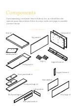
Page 2: ...teps on the next pages to assemble your new dresser Outer body of dresser Draws Base x 1 Side panel x 2 Support beam x 2 Base large x 2 Base small x 2 Support beam x 2 Leg x 4 Middle panel x 1 Front p...

Page 3: ...Hardware You will need...

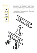
Page 4: ...screw C in the two outer holes Align the front support beam perpendicular to the support beam 2 and firmly press together Insert a cam lock E in both of the holes on the support beam 1 as shown in the...

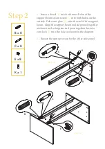
Page 5: ...ew C into both holes on the outside Dab some glue K onto the end of the support beam Align the support beam and side panel together as shown in the diagram and press together Insert a cam lock E into...

Page 6: ...base and cam screws C into the outer holes 3 2 Align the structure formed in Step 2 to the base and firmly press together On the inside of the structure insert a cam lock E into each of the four hole...

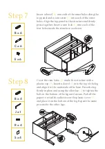
Page 7: ...wel A in each of the three holes on the top of the first back panel Align the second half of the back panel to the structure with the holes facing downward and gently slide along the grooves firmly pr...

Page 8: ...he outer hole Align the middle panel inside the top tier of the structure and firmly press the middle panel to the top support beam Insert a cam lock E into the hole as shown in the diagram Align a tr...

Page 9: ...8 Cover the cam locks E inside the structure with a plastic cap R Insert a dowel B into the top of the leg and align it to the underside of the base Press the leg firmly in place and using the allen...

Page 10: ...ole on the end of each panel Step 10 Insert a dowel A into the middle hole on either side of the back side panel of the draw Align the side panel to the back and firmly press together Insert a screw I...

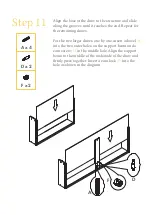
Page 11: ...maining draws For the two larger draws one by one insert a dowel A into the two outer holes on the support beam and a cam screw D in the middle hole Align the support beam to the middle of the undersi...

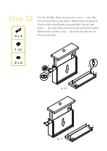
Page 12: ...four holes on the panel Align the front panel to the structure and firmly press together Insert cam locks F into the holes on the outside of the structure followed by a plastic cap R Repeat the proce...

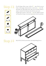
Page 13: ...middle hole Then follow the same process from the last step to attach the front panel to the structure not forgetting to insert a cam lock F into the support beam at the end of the process and repeat...

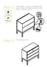
Page 14: ...Step 15 Place a stopper L along the side of the back of the dresser as shown in the diagram and follow it with a screw M to secure it in place Step 16 Enjoy your new dresser L x 6 M x 6 M L...

Reviews: