


3
BAS-6150
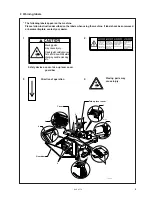
Do not touch any of the moving parts nor press
any objects against the machine in operation.
Any touch or press may cause damage to the
machine or injury to human body.
Do not put objects or a screwdriver in the
exhaustion outlet or inside the machine. Ac-
cidental touch on an area with high voltage
may cause electrical shock.
Do not damage, process, heat, and apply ex-
cessive force to the power cord or other wir-
ing cords. Breakage of the power cord and
other wiring cords may cause fire or electric
shock.
Turn off the power switch when the control
unit is subject to water or chemicals. Con-
tinuous operation of the control unit sub-
jected to water or chemicals may cause fire
or electrical shock.
Turn off the power switch when incorrect
operation and abnormal sound or smell are
noticed. Contact your Brother dealer or a
qualified technician.
Contact your Brother dealer or a qualified
technician when the machine is in trouble.
Sewing
The machine should be operated only by
operators who have been trained for safety
operation.
Do not let children access to the machine.
The machine should not be used for any other
application than sewing.
Be sure to wear protective goggles when
operating the machine. Otherwise, a broken
needle may get in your eyes and cause in-
jury.
Turn off the power on the following occa-
sions. Otherwise, unintended press on the
foot switch may cause injury.
• When replacing a needle
• When not operating the machine and leav-
ing it unattended
Do not operate the machine where an aerosol
product (air spray) is used or where oxygen is
being administered.
Attach all safety devices before using the
machine. Operation without safety device
may cause injury.
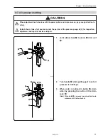
CAUTION
Summary of Contents for BAS-6150
Page 2: ......
Page 11: ...Chapter 1 Machine Preparation ...
Page 29: ...Chapter 2 Sewing flow ...
Page 41: ...Chapter 3 Settings ...
Page 55: ...Chapter 4 Oiling ...
Page 59: ...Chapter 5 Adjustment For raising the head refer to 3 How to raisethehead in Chapter4 Oiling ...
Page 70: ...Chapter 5 Adjustment BAS 6150 68 ...
Page 71: ...Chapter 6 Knife replacement ...
Page 77: ...Chapter 7 Environment setting ...
Page 85: ...Chapter 7 Environment setting BAS 6150 83 Standard stacker 4 steps 0 1 3 4 2 1530S ...
Page 95: ...Chapter 8 Dipswitch ...
Page 98: ...Chapter 8 Dipswitch BAS 6150 96 ...
Page 99: ...Chapter 9 Error code List ...
Page 103: ...Chapter 10 Troubleshooting ...


