


Chapter 5 Adjustment
BAS-6150
63
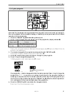
7-2. How to set the detection sensitivity
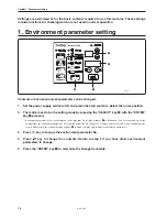
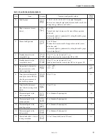
7-2-1. Threshold value setting
1mm
t
w
q
e
r
y
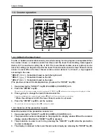
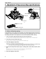
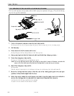
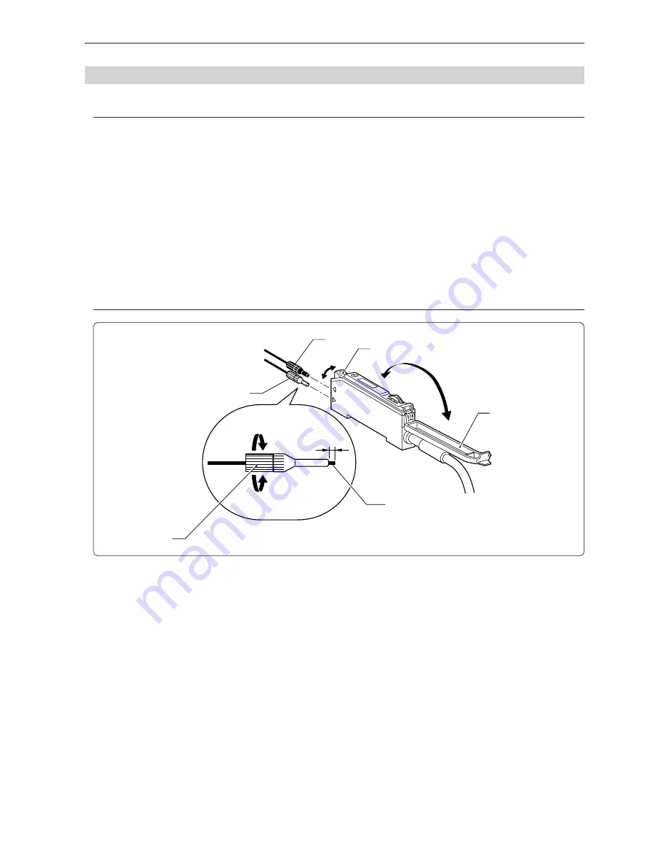
1.
Dismount cover
q
for the sensor amplifier. Pull down lever
w
and pull out fiber
e
.
2.
Rotate sleeve
r
by the base and loosen fiber
e
.
3.
Adjust the top of the fiber to come out about 1mm from the sleeve and turn the sleeve base to
fix.
4.
Put fiber at light projection side (black sleeve)
t
into the upper side of amplifier.
5.
Put fiber at light receive side (gray sleeve)
y
into the lower side of amplifier.
6.
Pull up lever
w
and mount cover
q
for the sensor amplifier.
(Note) Be sure to cut the top of fiber only by the dedicated fiber cutter, which comes with at supply of the fiber.
Cutting by a nipper and other tools may cause low sensitivity and detection error.
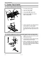
Perform the following adjustment for left and right sensors.
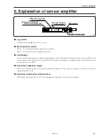
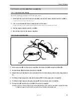
1.
Dismount the cover for the sensor amplifier and set the mode selection switch to [SET].
Confirm the detection output is selected to be [1].
2.
The current threshold value is displayed in LED screen.
Decrease the value (200-300) when the reflected light is not strong enough and a detection error occurs.
3.
Set the mode selection switch to [RUN].
4.
Mount the cover for the sensor amplifier.
7-2-2. How to insert the fiber
1503S
Summary of Contents for BAS-6150
Page 2: ......
Page 11: ...Chapter 1 Machine Preparation ...
Page 29: ...Chapter 2 Sewing flow ...
Page 41: ...Chapter 3 Settings ...
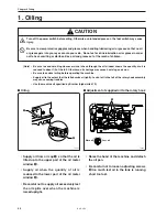
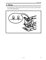
Page 55: ...Chapter 4 Oiling ...
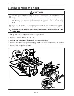
Page 59: ...Chapter 5 Adjustment For raising the head refer to 3 How to raisethehead in Chapter4 Oiling ...
Page 70: ...Chapter 5 Adjustment BAS 6150 68 ...
Page 71: ...Chapter 6 Knife replacement ...
Page 77: ...Chapter 7 Environment setting ...
Page 85: ...Chapter 7 Environment setting BAS 6150 83 Standard stacker 4 steps 0 1 3 4 2 1530S ...
Page 95: ...Chapter 8 Dipswitch ...
Page 98: ...Chapter 8 Dipswitch BAS 6150 96 ...
Page 99: ...Chapter 9 Error code List ...
Page 103: ...Chapter 10 Troubleshooting ...