5-6
Confidential
1.3.2
Creating of Head Calibration Data and Writing it into Flash ROM
(Maintenance mode 02)
< Function >
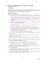
This procedure scans the "Print pattern for creating head calibration data" sheets (see
)
placed on the scanner glass of the document cover, creates the head calibration data using the
scanning result, and writes it into the flash ROM on the main PCB.
< Operating Procedure >
Notes
• Before proceeding to the procedure given below, use
Section 1.3.5 "Printout of Test
Pattern (Maintenance mode 09)"
in this chapter to check that there is no block missing.
• Before proceeding to the procedure given below, use
Section 1.3.35 "Assurance Mode
Switch Setting (Maintenance mode 88)"
in this chapter to check that the uneven
printing correction for upper and lower ends of the nozzle is set to ON (Selector 1 on
AMS05 is "0").
• Before proceeding to the procedure given below, use the following to enable the
machine to make high precision printing.
• Make sure that both the document scanner unit and document cover are closed.
• For higher precision of uneven printing correction, it is recommended to use the
recording paper specified below to print the pattern for creating head calibration data.
US: Xerox 4200DP 20 lb., Brother BP60PL
EU, AP and others: Xerox Business 80 g/m
2
, Brother BP60PA
(1) Save copies of "head_calib1_BHS13.prn" and "head_calib2_BHS13.prn" to a USB
memory or SD card.
(2) Use
Section 1.3.21 "Printout of PRN/JPEG Files in Memory Card (Maintenance mode 61)"
to print two file patterns (2 sheets).
(3) Fold the printed patterns for creating head calibration data along the folding line. (See
.)
(4) Set the pattern printed with "1_page" on the scanner glass of the document cover so that the
mark fits on the left rear of the document cover.
(5) Press the
0
and
2
keys in this order in the initial stage of the maintenance mode.
The "MAINTENANCE 02" and "No. 1 Sheet Set" appear on the LCD in this order.
Note:
Pressing the
Stop
key immediately returns the machine to the initial stage of the
maintenance mode without creating head calibration data.
(6) Press the
Mono Start
key.
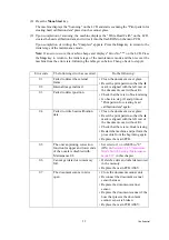
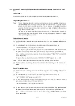
The machine displays the "Scanning" on the LCD and starts scanning the "Print pattern for
creating head calibration data" placed on the scanner glass.
(7) If "No. 2 Sheet Set" appears on the LCD, remove the pattern printed with "1_page" from
the scanner glass and set the pattern printed with "2_page."
Summary of Contents for Business Smart MFC-J4510dw
Page 18: ...xv Confidential ...
Page 19: ...xvi Confidential ...
Page 20: ...xvii Confidential ...
Page 22: ...xix Confidential ...
Page 23: ...xx Confidential ...
Page 24: ...xxi Confidential ...
Page 51: ...Confidential 2 14 Error Code Contents Refer to page FE ROM data acquisition error 2 57 ...
Page 130: ...3 3 Confidential 2 PACKING 3_131_E ...
Page 153: ...3 26 Confidential 3 Set the protective part 3_002_E Protective part ...
Page 265: ...4 11 Confidential ADF Copy Chart A B C ...
Page 292: ...5 13 Confidential Scanning Compensation Data List ...
Page 294: ...5 15 Confidential Test Pattern ...
Page 317: ...5 38 Confidential pfadj1 Pattern ...
Page 318: ...5 39 Confidential pfadj2 Pattern ...
Page 324: ...5 45 Confidential Vertical Lines Check Pattern ...
Page 325: ...5 46 Confidential Software Correction for Inclination Corrugation Ruled Lines Check Pattern ...

