App. 1-9
Confidential
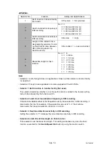
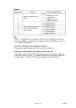
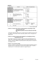
<WSW05>
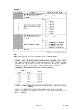
Note:
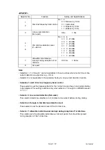
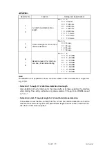
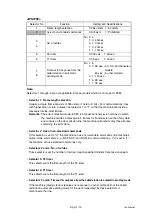
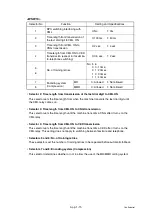
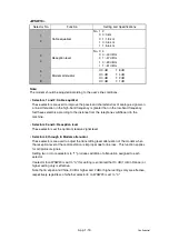
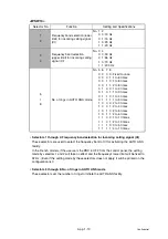
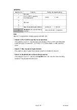
Selectors 5 through 7 are not applicable in those countries where no busy tone detection is
supported.
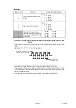
• Selectors 1 through 3: 1st dial tone detection
These selectors activate or deactivate the 1st dial tone detection function which detects the
1st dial tone issued from the PSTN when a line is connected to the PSTN.
Setting all of these selectors to "1" activates the dial tone detection function so that the
machine starts dialing upon detection of a dial tone when a line is connected. (However, in
those countries which support no dial tone detection function, e.g., in the U.S.A., setting
these selectors to "1" makes the machine start dialing after a WAIT of 3.5 seconds.) For the
detecting conditions of the 1st dial tone, refer to WSW07 and WSW08.
Other setting combinations deactivate the dial tone detection function so that the machine
starts dialing after the specified WAIT (3.5, 7.0, 10.5, 14.0, 17.5, 21.0, or 24.5 seconds)
without detection of a dial tone when a line is connected to the PSTN.
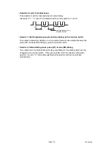
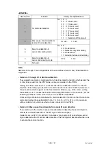
• Selector 4: Max. pause time allowable for remote ID code detection
This selector sets the maximum pause time allowable for detecting the second digit of a
remote ID code after detection of the first digit in remote reception.
If selector 4 is set to "0" (2 seconds), for instance, only a remote ID code whose second
digit is detected within 2 seconds after detection of the first digit will become effective so as
to activate the remote function.
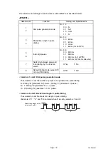
Selector No.
Function
Setting and Specifications
1
I
3
1st dial tone detection
No. 1 2 3
0 0 0: 3.5 sec. wait
0 0 1: 7.0 sec. wait
0 1 0: 10.5 sec. wait
0 1 1: 14.0 sec. wait
1 0 0: 17.5 sec. wait
1 0 1: 21.0 sec. wait
1 1 0: 25.0 sec. wait
1 1 1: Detection (Without wait)
4
Max. pause time allowable for
remote ID code detection
0: 2 sec.
1: 1 sec.
5
6
Busy tone detection in
auto-matic sending mode
No. 5 6
0 0: No detection
0 1: Detection only after dialing
1 0: No detection
1 1: Detection before and after dialing
7
Busy tone detection in
auto-matic receiving mode
0: Yes
1: No
8
Not used.
Summary of Contents for DCP-7030
Page 201: ...5 5 Confidential Print sample Fig 5 1 ...
Page 226: ...5 30 Confidential Location of fans Fig 5 13 Fan motor 60 unit Right side ...
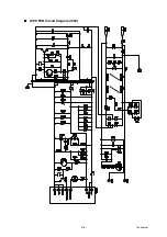
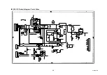
Page 234: ...6 2 Confidential LVPS PCB Circuit Diagram 100V ...
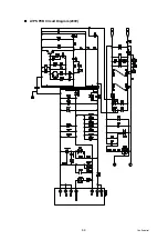
Page 235: ...6 3 Confidential LVPS PCB Circuit Diagram 200V ...
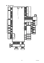
Page 239: ...6 7 Confidential Wiring Diagram ...

