App. 1-40
Confidential
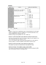
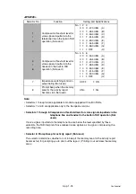
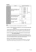
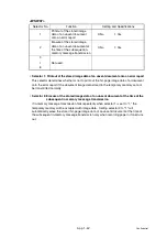
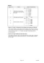
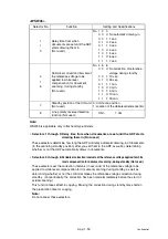
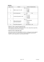
<WSW35>
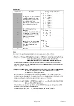
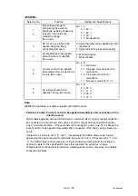
Note:
Selectors 1 through 4 are applicable to models equipped with internal TADs.
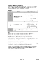
• Selectors 1 through 4: Max. detection period of dial tone/busy tone during recording
of ICM (Not used.)
If the machine (called station) detects dial tone or busy tone exceeding the detection level
specified by selectors 1 through 3 on WSW30 for the period specified by these selectors,
then it disconnects the line.
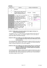
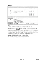
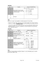
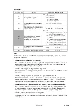
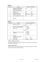
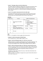
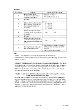
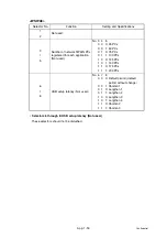
<WSW36>
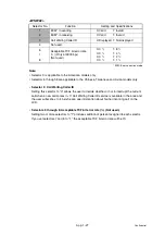
*ECP (Enhanced Capabilities Port)
Note:
Selectors 2 and 3 will become operative if selectors 1 and 2 of WSW46 are set to "monitor"
the PC power ON/OFF state.
Selector No.
Function
Setting and Specifications
1
I
4
Max. detection period of dial
tone/busy tone during recording
of ICM (Not used.)
No. 1 2 3 4
0 0 0 0: No detection
0 0 0 1: 1 sec.
0 0 1 0: 2 sec.
0 1 0 0: 4 sec.
|
1 1 1 1: 15 sec.
5
I
8
Not used.
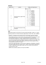
Selector No.
Function
Setting and Specifications
1
ECP mode* (Not used.)
0: ON
1: OFF
2
Recovery from Inactive PC
Interface (Not used.)
0: Disable
1: Enable
3
PC Power-off Recognition Time
(Not used.)
0: Normal
1: Long
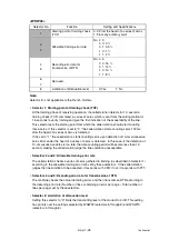
4
Not used.
5
Escape from phase C
0: Yes
1: No
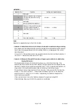
6
I
8
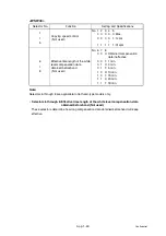
Extension of incoming calling
signal (CI) frequency band
specified by selectors 1 through
4 on WSW14
No. 6 7 8
0 0 0: 0
(Ignored)
0 0 1: 4
(448 Hz)
0 1 0: 8
(244 Hz)
0 1 1: 12
(162 Hz)
1 0 0: 16
(122 Hz)
1 0 1: 20
(97 Hz)
1 1 0: 24
(81 Hz)
1 1 1: 28
(69 Hz)
Summary of Contents for DCP-7030
Page 201: ...5 5 Confidential Print sample Fig 5 1 ...
Page 226: ...5 30 Confidential Location of fans Fig 5 13 Fan motor 60 unit Right side ...
Page 234: ...6 2 Confidential LVPS PCB Circuit Diagram 100V ...
Page 235: ...6 3 Confidential LVPS PCB Circuit Diagram 200V ...
Page 239: ...6 7 Confidential Wiring Diagram ...

