App. 1-50
Confidential
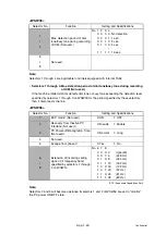
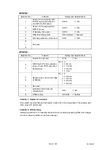
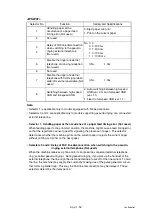
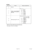
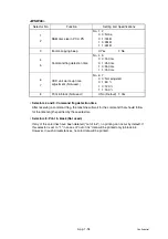
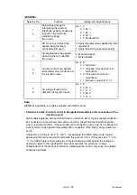
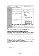
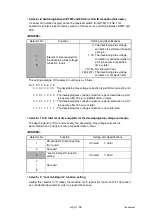
<WSW45>
Note:
WSW45 is applicable only to flat head-type models.
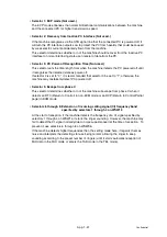
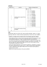
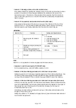
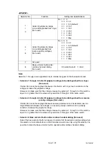
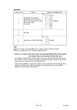
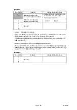
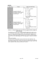
• Selectors 1 through 3: Delay time from when documents are set until the ADF starts
drawing them in (Not used.)
These selectors determine how long the ADF will delay automatic drawing-in of documents
(to the scanning standby position) after you set them in the ADF, as well as determining
whether or not the ADF automatically draws in documents.
• Selectors 4 through 6: Periodical correction intervals of the reference voltage applied to white
level compensation for document scanning, during standby (Not used.)
These selectors set the correction intervals (in seconds) of the reference voltage to be
applied to white level compensation for document scanning during standby, as well as
determining whether or not the controller makes the reference voltage correction during
standby. (Conventionally, the correction has been made immediately before the start of
actual scanning)
This function takes effect in copying. Making the correction during standby may shorten
the preparation time for copying.
Note:
Do not access these selectors.
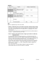
Selector No.
Function
Setting and Specifications
1
I
3
Delay time from when
documents are set until the ADF
starts drawing them in
(Not used.)
No. 1 2 3
0 0 0: No automatic drawing-in
0 0 1: 1 sec.
0 1 0: 2 sec.
0 1 1: 3 sec.
1 0 0: 4 sec.
1 0 1: 5 sec.
1 1 0: 6 sec.
1 1 1: 7 sec.
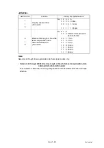
4
I
6
Periodical correction intervals of
the reference voltage to be
applied to white level
compensation for document
scanning, during standby
(Not used.)
No. 4 5 6
0 0 0: No correction of reference
voltage during standby
0 0 1: 10 sec.
0 1 0: 30 sec.
0 1 1: 1 min.
1 0 0: 3 min.
1 0 1: 5 min.
1 1 0: 10 min.
1 1 1: 30 min.
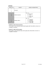
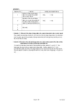
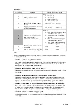
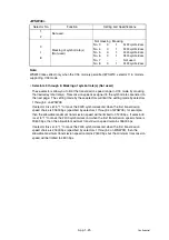
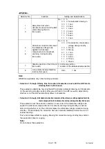
7
Standby position of the CIS unit
(Not used.)
0: CIS home position
1: Location of the white-level reference film
8
Line polarity reverse detection
function (Not used.)
0: No
1: Yes
Summary of Contents for DCP-7030
Page 201: ...5 5 Confidential Print sample Fig 5 1 ...
Page 226: ...5 30 Confidential Location of fans Fig 5 13 Fan motor 60 unit Right side ...
Page 234: ...6 2 Confidential LVPS PCB Circuit Diagram 100V ...
Page 235: ...6 3 Confidential LVPS PCB Circuit Diagram 200V ...
Page 239: ...6 7 Confidential Wiring Diagram ...

