App. 1-51
Confidential
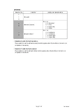
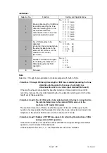
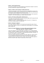
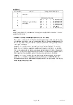
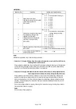
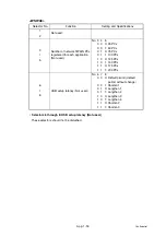
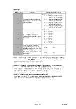
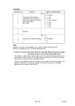
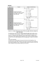
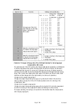
• Selector 7: Standby position of the CIS unit (Not used.)
This selector determines whether the standby position of the CIS unit should be the home
position or the location of the white-level reference film (attached to the inside of the
scanner top cover). If the location of the reference film is selected, the CIS unit will not
return to the home position so as to shorten the travel time, decreasing the preparation
time for copying.
• Selector 8: Line polarity reverse detection function (Not used.)
Line polarity will be reversed if the phone is hung up at the other end of the line. If this
selector is set to "1," the machine will detect the reverse polarity during an answering
machine operation and thereby determine that the phone has been hung up.
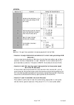
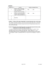
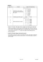
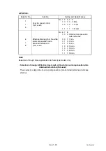
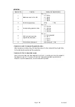
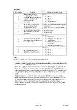
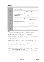
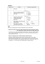
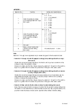
<WSW46>
Note:
Selector 4 is not applicable to models equipped with flat-bed scanners.
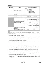
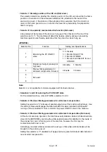
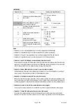
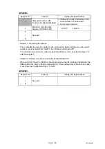
• Selectors 1 and 2: Monitoring the PC ON/OFF state
For the related functions, refer to WSW36, selectors 2 and 3.
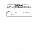
• Selector 3: Previous filtering parameters for white level compensation
Setting this selector to "0" will keep all parallel output pins of the machine at high level. Use
this setting if Resource Manager (bundled with MFC models) installed to WindowsNT
running on the connected PC fails to monitor the power ON/OFF state of the machine.
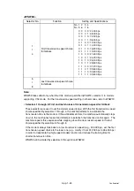
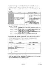
• Selector 4: Previous filtering parameters for white level compensation (Not used.)
At the start of scanning operation, the machine usually initializes white and black level data
stored in the EEPROM by scanning the while-level reference film attached to the inside of
the scanner top cover. After long use of the machine, however, the film may be
contaminated with dust or dirt.
Accordingly, incorrect white level data will be set up so that white vertical streaks will be
brought on the scanning result.
Setting this selector to "0" (Enabled) will apply previously saved white level data instead of
new incorrect compensation.
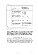
Selector No.
Function
Setting and Specifications
1
2
Monitoring the PC ON/OFF
state
No. 1 2
0 0: Disable
0 1: Monitor SELECT IN
1 0: Monitor STROBE
1 1: Monitor both SELECT IN and
STROBE
3
Parallel port output pins kept at
high level
0: Enable
1: Disable
4
Previous filtering parameters for
white level compensation (Not used.)
0: Enable
1: Disable
5
I
8
Not used.
Summary of Contents for DCP-7030
Page 201: ...5 5 Confidential Print sample Fig 5 1 ...
Page 226: ...5 30 Confidential Location of fans Fig 5 13 Fan motor 60 unit Right side ...
Page 234: ...6 2 Confidential LVPS PCB Circuit Diagram 100V ...
Page 235: ...6 3 Confidential LVPS PCB Circuit Diagram 200V ...
Page 239: ...6 7 Confidential Wiring Diagram ...

