MFC-8440/8840D/8840DN, DCP-8040/8045D/8045DN
SERVICE MANUAL
5-1
CHAPTER 5 PERIODIC MAINTENANCE
To avoid creating secondary problems by mishandling, follow the warnings below during
maintenance work.
WARNING
(1) Always turn off the power switch and unplug the power cord from the power outlet
before accessing any parts inside the machine.
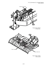
(2) Some parts inside the machine are extremely hot immediately after the machine is
used. When opening the front cover or rear cover to access any parts inside the
machine, never touch the shaded parts shown in the following figures.
1. CONSUMABLE PARTS
The consumable parts described in this section are parts which are subject to deterioration or
damage and should be replaced at least once during the period of warranty of the product if
any print quality problem appears.
1.1 Drum
Unit
Life expectancy:
20,000 pages
(When printing A4 or Letter size paper at 5% print coverage)
*The actual number of printed pages will vary depending on the
average type of print job and paper.
NOTE:
•
There are many factors that determine the actual drum life, such as temperature, humidity,
type of paper, type of toner used, number of pages per print job and so on. Under ideal
conditions, the average drum life is estimated at up to 20,000 pages. The actual number
of pages that your drum will print may be significantly less than this estimate. Because we
have no control over the many factors that determine the actual drum life, we cannot
guarantee a minimum number of pages that will be printed by your drum.
•
For best performance, use only genuine Brother toner. The machine should be used only
in a clean, dust-free environment with adequate ventilation.
•
Printing with a third-party drum unit may reduce not only the print quality but also the
quality and life of the machine itself. Warranty coverage does not apply to problems
caused by the use of third-party drum unit.
Summary of Contents for DCP-8040
Page 276: ...CHAPTER 7 MAINTENANCE MODE 7 6 Fig 7 3 l m a b c d e f g h i j k ...
Page 347: ...APPENDIX 4 CIRCUIT DIAGRAMS A 50 Appendix 4 1 Main PCB Circuit Diagram 1 7 ...
Page 349: ...APPENDIX 4 CIRCUIT DIAGRAMS A 52 Appendix 4 3 Main PCB Circuit Diagram 3 7 ...
Page 351: ...APPENDIX 4 CIRCUIT DIAGRAMS A 54 Appendix 4 5 Main PCB Circuit Diagram 5 7 ...
Page 353: ...APPENDIX 4 CIRCUIT DIAGRAMS A 56 Appendix 4 7 Main PCB Circuit Diagram 7 7 ...
Page 355: ...APPENDIX 4 CIRCUIT DIAGRAMS A 58 Appendix 4 9 Engine PCB Circuit Diagram 1 2 ...
Page 357: ...APPENDIX 4 CIRCUIT DIAGRAMS A 60 Appendix 4 11 NCU PCB Circuit Diagram U S A ...
Page 359: ...APPENDIX 4 CIRCUIT DIAGRAMS A 62 Appendix 4 13 NCU PCB Circuit Diagram Asia ...
Page 361: ...APPENDIX 4 CIRCUIT DIAGRAMS A 64 Appendix 4 15 Control Panel PCB Circuit Diagram ...
Page 367: ...April 04 SM FAX027 5 8C5903 Printed in Japan ...

