CHAPTER 6 TROUBLESHOOTING
6-8
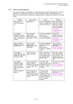
Error
Code
(Hex)
Error factor
Check:
73
Drum unit is not mounted.
•
Toner sensor
•
Drum unit
74
Toner empty.
•
Toner sensor
•
Toner cartridge
75
In-casing temperature error.
•
Thermistor ASSY
76
Heater harness disconnected or broken.
•
Thermistor ASSY
•
Halogen lamp
78
Heater thermistor harness disconnected or
broken.
•
Thermistor ASSY
79
In-casing temperature sensor harness
disconnected or broken.
7A
Main motor does not synchronize with the
reference clock.
7B
ASIC error on the main PCB.
7C
Engine PCB error.
•
Thermistor ASSY
•
Main PCB
•
Engine PCB
•
Main motor
80
At the start of recording operation, the
controller detects that paper is smaller than
A4 size in length or width.
•
Paper size
•
Front registration sensor
81
Paper jam.
•
Jammed paper
82
Paper feeding error.
•
Paper pick up roller
83
Recording paper jam.
(At the retry of paper pulling-in operation,
the registration sensor is not OFF.)
•
Registration sensor
•
Main PCB
84
Recording paper jam.
(The registration sensor has detected a
paper jam.)
•
Registration sensor actuator
•
Main PCB
85
No paper cassette loaded.
86
No 2nd paper cassette loaded.
87
Main motor stop position error.
•
Main motor
88
Recording paper jam.
(Even after paper pulling-in operation, the
registration sensor is still OFF.)
•
Registration sensor actuator
•
Main PCB
A1
Front cover opened.
•
Front cover sensor
•
Main PCB
Summary of Contents for DCP-8040
Page 276: ...CHAPTER 7 MAINTENANCE MODE 7 6 Fig 7 3 l m a b c d e f g h i j k ...
Page 347: ...APPENDIX 4 CIRCUIT DIAGRAMS A 50 Appendix 4 1 Main PCB Circuit Diagram 1 7 ...
Page 349: ...APPENDIX 4 CIRCUIT DIAGRAMS A 52 Appendix 4 3 Main PCB Circuit Diagram 3 7 ...
Page 351: ...APPENDIX 4 CIRCUIT DIAGRAMS A 54 Appendix 4 5 Main PCB Circuit Diagram 5 7 ...
Page 353: ...APPENDIX 4 CIRCUIT DIAGRAMS A 56 Appendix 4 7 Main PCB Circuit Diagram 7 7 ...
Page 355: ...APPENDIX 4 CIRCUIT DIAGRAMS A 58 Appendix 4 9 Engine PCB Circuit Diagram 1 2 ...
Page 357: ...APPENDIX 4 CIRCUIT DIAGRAMS A 60 Appendix 4 11 NCU PCB Circuit Diagram U S A ...
Page 359: ...APPENDIX 4 CIRCUIT DIAGRAMS A 62 Appendix 4 13 NCU PCB Circuit Diagram Asia ...
Page 361: ...APPENDIX 4 CIRCUIT DIAGRAMS A 64 Appendix 4 15 Control Panel PCB Circuit Diagram ...
Page 367: ...April 04 SM FAX027 5 8C5903 Printed in Japan ...


