CHAPTER 6 TROUBLESHOOTING
6-46
NOTE:
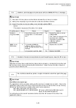
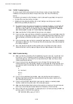
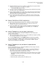
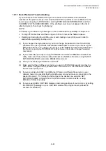
Clean the drum unit as follows:
(1) Remove the toner cartridge from the drum unit. Place the printing samples in front of the
drum unit, and find the exact position of the image defect.
Fig. 6-15
(2) Turn the drum gear by hand while looking at the surface of the photosensitive drum.
Fig. 6-16
(3) Wipe the surface of the photosensitive drum with a cotton swab until the dust or paper
powder on the surface comes off.
Fig. 6-17
!
CAUTION:
•
Do not wipe the surface of the photosensitive drum with something sharp. (ball-point pen
etc.)
•
Use cleaning liquid which is a 50-50 mixture of ethyl alcohol and pure water.
Position of smudge on
the drum
94mm interval
Printing sample
Drum unit
Photosensitive drum
Photosensitive drum
Summary of Contents for DCP-8040
Page 276: ...CHAPTER 7 MAINTENANCE MODE 7 6 Fig 7 3 l m a b c d e f g h i j k ...
Page 347: ...APPENDIX 4 CIRCUIT DIAGRAMS A 50 Appendix 4 1 Main PCB Circuit Diagram 1 7 ...
Page 349: ...APPENDIX 4 CIRCUIT DIAGRAMS A 52 Appendix 4 3 Main PCB Circuit Diagram 3 7 ...
Page 351: ...APPENDIX 4 CIRCUIT DIAGRAMS A 54 Appendix 4 5 Main PCB Circuit Diagram 5 7 ...
Page 353: ...APPENDIX 4 CIRCUIT DIAGRAMS A 56 Appendix 4 7 Main PCB Circuit Diagram 7 7 ...
Page 355: ...APPENDIX 4 CIRCUIT DIAGRAMS A 58 Appendix 4 9 Engine PCB Circuit Diagram 1 2 ...
Page 357: ...APPENDIX 4 CIRCUIT DIAGRAMS A 60 Appendix 4 11 NCU PCB Circuit Diagram U S A ...
Page 359: ...APPENDIX 4 CIRCUIT DIAGRAMS A 62 Appendix 4 13 NCU PCB Circuit Diagram Asia ...
Page 361: ...APPENDIX 4 CIRCUIT DIAGRAMS A 64 Appendix 4 15 Control Panel PCB Circuit Diagram ...
Page 367: ...April 04 SM FAX027 5 8C5903 Printed in Japan ...


