MFC-8440/8840D/8840DN, DCP-8040/8045D/8045DN
SERVICE MANUAL
A-1
APPENDIX 1 EEPROM CUSTOMIZING CODES
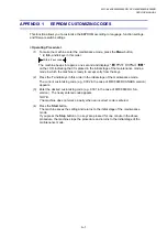
This function allows you to customize the EEPROM according to language, function settings,
and firmware switch settings.
< Operating Procedure >
(1) To make the machine enter the maintenance mode, press the
Menu
button,
*,
2, 8, 6,
and
4
keys in this order.
Within 2 seconds
The machine beeps for approx. one second and displays "
"
on the LCD, indicating that it is placed in the initial stage of the maintenance mode, a
mode in which the machine is ready to accept entry from the keys.
(2) Press
the
7
and
4
keys in this order in the initial stage of the maintenance mode.
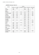
The current customizing code (e.g., 0302 in the case of MFC8840D CANADA version)
appears.
(3) Enter the desired customizing code (e.g., 9301 in the case of MFC8840D U.S.A.
version). The newly entered code appears.
NOTE:
The machine does not work properly when an incorrect code is entered.
(4) Press
the
Start
button.
The machine saves the setting and returns to the initial stage of the maintenance
mode.
If you press the
Stop
button or no keys are pressed for one minute in the above
procedure, the machine stops the procedure and returns to the initial stage of the
maintenance mode.
Summary of Contents for DCP-8040
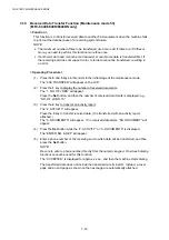
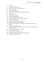
Page 276: ...CHAPTER 7 MAINTENANCE MODE 7 6 Fig 7 3 l m a b c d e f g h i j k ...
Page 347: ...APPENDIX 4 CIRCUIT DIAGRAMS A 50 Appendix 4 1 Main PCB Circuit Diagram 1 7 ...
Page 349: ...APPENDIX 4 CIRCUIT DIAGRAMS A 52 Appendix 4 3 Main PCB Circuit Diagram 3 7 ...
Page 351: ...APPENDIX 4 CIRCUIT DIAGRAMS A 54 Appendix 4 5 Main PCB Circuit Diagram 5 7 ...
Page 353: ...APPENDIX 4 CIRCUIT DIAGRAMS A 56 Appendix 4 7 Main PCB Circuit Diagram 7 7 ...
Page 355: ...APPENDIX 4 CIRCUIT DIAGRAMS A 58 Appendix 4 9 Engine PCB Circuit Diagram 1 2 ...
Page 357: ...APPENDIX 4 CIRCUIT DIAGRAMS A 60 Appendix 4 11 NCU PCB Circuit Diagram U S A ...
Page 359: ...APPENDIX 4 CIRCUIT DIAGRAMS A 62 Appendix 4 13 NCU PCB Circuit Diagram Asia ...
Page 361: ...APPENDIX 4 CIRCUIT DIAGRAMS A 64 Appendix 4 15 Control Panel PCB Circuit Diagram ...
Page 367: ...April 04 SM FAX027 5 8C5903 Printed in Japan ...


