APPENDIX 3 FIRMWARE SWITCHS (WSW)
A-22
WSW15 (REDIAL facility setting)
Selector
No.
Function
Setting and Specifications
1
2
Selection of redial interval
No. 1 2
0 0 : 5
minutes
0 1 : 1
minute
1 0 : 2
minutes
1 1 : 3
minutes
3
|
6
No. of redialings
No.
3 4 5 6
0 0 0 0 : 16
times
0 0 0 1 :
1
times
0 0 1 0 : 2
times
0 0 1 1 : 3
times
|
|
1 1 1 1 : 15
times
7
Redialing for no response sent
from the called terminal
0: Redialing 1: No
redialing
8 CRP
option
0: Disable
1: Enable
l
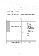
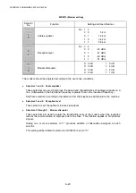
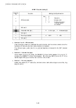
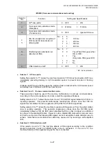
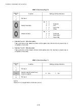
Selectors 1 through 6: Selection of redial interval and No. of redialings
The machine redials by the number of times set by selectors 3 through 6 at intervals set by
selectors 1 and 2.
This setting is effective only when selector 7 is set to "0."
l
Selectors 7: Redialing for no response sent from the called terminal
This selector determines whether or not the machine redials if no G3 command response
comes from the called station after dialing within the time length set by selectors 7 and 8 of
WSW09.
l
Selectors 8: CRP option
If a command error occurs in the equipment (calling station), the equipment usually waits for
three seconds and then makes a retry three times. This CRP option is a request command
that can be sent from the called station for requesting the calling station to retry the failed
command immediately.
Summary of Contents for DCP-8040
Page 276: ...CHAPTER 7 MAINTENANCE MODE 7 6 Fig 7 3 l m a b c d e f g h i j k ...
Page 347: ...APPENDIX 4 CIRCUIT DIAGRAMS A 50 Appendix 4 1 Main PCB Circuit Diagram 1 7 ...
Page 349: ...APPENDIX 4 CIRCUIT DIAGRAMS A 52 Appendix 4 3 Main PCB Circuit Diagram 3 7 ...
Page 351: ...APPENDIX 4 CIRCUIT DIAGRAMS A 54 Appendix 4 5 Main PCB Circuit Diagram 5 7 ...
Page 353: ...APPENDIX 4 CIRCUIT DIAGRAMS A 56 Appendix 4 7 Main PCB Circuit Diagram 7 7 ...
Page 355: ...APPENDIX 4 CIRCUIT DIAGRAMS A 58 Appendix 4 9 Engine PCB Circuit Diagram 1 2 ...
Page 357: ...APPENDIX 4 CIRCUIT DIAGRAMS A 60 Appendix 4 11 NCU PCB Circuit Diagram U S A ...
Page 359: ...APPENDIX 4 CIRCUIT DIAGRAMS A 62 Appendix 4 13 NCU PCB Circuit Diagram Asia ...
Page 361: ...APPENDIX 4 CIRCUIT DIAGRAMS A 64 Appendix 4 15 Control Panel PCB Circuit Diagram ...
Page 367: ...April 04 SM FAX027 5 8C5903 Printed in Japan ...


