1-5
Confidential
2.2
Functions
<Controller>
Specifications are subject to change without notice.
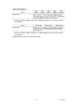
Model
DCP
8080DN
DCP
8085DN
MFC
8480DN
MFC
8880DN
MFC
8890DW
CPU
300 MHz
Back up Clock
Yes (up to 60 hours)
Memory
Standard
64 MB
Option
1 DIMM slot; expandable up to 576 MB
Backup
No
Yes (up to 60 hours)
Interface
IEEE 1284 Parallel, Hi-Speed USB 2.0,
Ethernet 10/100 BASE-TX, USB Host
IEEE 1284
Parallel,
Hi-Speed
USB 2.0,
Ethernet
10/100
BASE-TX,
Wireless
LAN IEEE
802.11b/g,
USB Host
Emulation
PCL6, BR-Script 3 (PostScript
®
3™), IBM Pro-printer XL,
Epson FX-850
Network
Connectivity
Protocol
TCP/IP(10/100 BASE-TX Ethernet)
Management tool BRAdmin Light, Web BRAdmin, Web Based
Management , BRAdmin Professional 3
Resident fonts
PCL
66 scalable fonts, 12 bitmap fonts, 13 bar codes
BR-Script 3
(PostScript
®
3™)
66 scalable fonts
Summary of Contents for DCP 8085DN
Page 13: ...CHAPTER 1 SPECIFICATIONS ...
Page 52: ...Confidential CHAPTER 2 THEORY OF OPERATION ...
Page 69: ...2 16 Confidential 3 3 Paper Feeding Fig 2 18 LT path DX path MP path Paper tray path ...
Page 89: ...CHAPTER 3 ERROR INDICATION AND TROUBLESHOOTING ...
Page 178: ...Confidential CHAPTER 4 PERIODICAL MAINTENANCE ...
Page 248: ...CHAPTER 5 DISASSEMBLY REASSEMBLY ...
Page 265: ...5 12 Confidential Fig 5 7 EM2 4 places Separation pad ASSY ...
Page 501: ...Confidential CHAPTER 6 ADJUSTMENTS AND UPDATING OF SETTINGS REQUIRED AFTER PARTS REPLACEMENT ...
Page 507: ...6 5 Confidential 8 Alert warning message of WHQL appears Click Continue Anyway to proceed ...
Page 516: ...CHAPTER 7 SERVICE MODE ...
Page 525: ...7 7 Confidential For color scanning Fig 7 2 ...
Page 527: ...7 9 Confidential For white and black scanning Fig 7 3 ...
Page 528: ...7 10 Confidential For color scanning Fig 7 4 ...
Page 567: ...Confidential CHAPTER 8 CIRCUIT DIAGRAMS WIRING DIAGRAM ...
Page 569: ...8 1 Confidential 1 CIRCUIT DIAGRAMS High voltage Power Supply PCB Circuit Diagram Fig 8 1 ...
Page 570: ...8 2 Confidential LVPS PCB Circuit Diagram 230V Fig 8 2 ...
Page 571: ...8 3 Confidential LVPS PCB Circuit Diagram 115V Fig 8 3 ...

