6-3
Confidential
• If rewriting the firmware files
If rewriting the firmware using a USB flash memory drive fails in process and an error
message appears on the LCD, or no message appears on the LCD, it will be necessary to
rewrite the firmware using the “FILEDG32.EXE”. Follow the steps below.
< Installing the maintenance driver >
To identify machines connected via USB direct interface, the PC requires the
corresponding driver for the virtual USB device. If you connect any number of machines to
your PC, the same number of virtual USB devices will be automatically configured on your
PC. To prevent many virtual USB devices from being configured, use the unique driver
installation procedure described below that enables your PC to identify terminals via one
single virtual USB device.
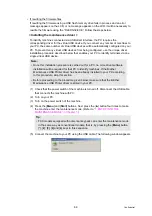
(1) Check that the power switch of the machine is turned off. Disconnect the USB cable
that connects the machine with PC.
(2) Turn on your PC.
(3) Turn on the power switch of the machine.
(4) Press the [
Menu
] and [
Start
] buttons. Next press the [ ] button four times to make
the machine enter the maintenance mode. (Refer to
MAINTENANCE MODE" in Chapter 7
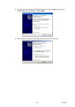
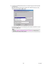
(5) Connect the machine to your PC using the USB cable. The following window appears.
Note;
• Once this installation procedure is carried out for a PC, no more driver/software
installation will be required for that PC to identify machines. If the Brother
Maintenance USB Printer driver has been already installed to your PC according
to this procedure, skip this section.
• Before proceeding to the procedure given below, make sure that the Brother
Maintenance USB Printer driver is stored in your PC.
Tip;
• FAX models equipped with numerical keypads can enter the maintenance mode
in the same way as conventional models; that is, by pressing the [
Menu
] button,
[
*
], [
2
], [
8
], [
6
] and [
4
] keys in this sequence.
Summary of Contents for DCP 8085DN
Page 13: ...CHAPTER 1 SPECIFICATIONS ...
Page 52: ...Confidential CHAPTER 2 THEORY OF OPERATION ...
Page 69: ...2 16 Confidential 3 3 Paper Feeding Fig 2 18 LT path DX path MP path Paper tray path ...
Page 89: ...CHAPTER 3 ERROR INDICATION AND TROUBLESHOOTING ...
Page 178: ...Confidential CHAPTER 4 PERIODICAL MAINTENANCE ...
Page 248: ...CHAPTER 5 DISASSEMBLY REASSEMBLY ...
Page 265: ...5 12 Confidential Fig 5 7 EM2 4 places Separation pad ASSY ...
Page 501: ...Confidential CHAPTER 6 ADJUSTMENTS AND UPDATING OF SETTINGS REQUIRED AFTER PARTS REPLACEMENT ...
Page 507: ...6 5 Confidential 8 Alert warning message of WHQL appears Click Continue Anyway to proceed ...
Page 516: ...CHAPTER 7 SERVICE MODE ...
Page 525: ...7 7 Confidential For color scanning Fig 7 2 ...
Page 527: ...7 9 Confidential For white and black scanning Fig 7 3 ...
Page 528: ...7 10 Confidential For color scanning Fig 7 4 ...
Page 567: ...Confidential CHAPTER 8 CIRCUIT DIAGRAMS WIRING DIAGRAM ...
Page 569: ...8 1 Confidential 1 CIRCUIT DIAGRAMS High voltage Power Supply PCB Circuit Diagram Fig 8 1 ...
Page 570: ...8 2 Confidential LVPS PCB Circuit Diagram 230V Fig 8 2 ...
Page 571: ...8 3 Confidential LVPS PCB Circuit Diagram 115V Fig 8 3 ...

