2-25
Confidential
3.4.3 New toner detection
This machine is equipped with the function to detect that the residual quantities of the toner
are not enough by examining the degree that the toner in the cartridge blocks the light by the
transmission light sensor. This function informs the user's that the toner cartridge has reached
its life. However there is a description such as previous contents when the toner cartridge
reaches itself the life end by the abrasion of the rollers, "the toner is life end" is displayed on
the LCD and stops moving itself to promote the replacement of the new one even if the
remaining amount of the toner is enough. At this time, the toner LED sensor cannot check the
attachment of a new toner. There is a possibility that the image quality decrease and the toner
leakage occur if the cartridge that reaches longevity is continuously used. Therefore it is
necessary to remove the movement stop state when a new toner is attached to the machine.
It is new toner detection mechanism to explain here to enable this distinction.
The new toner detection can distinguish the standard toner and high yield toner cartridge.
The new toner detection is performed by the following procedure.
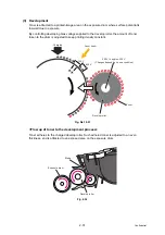
(1) The main motor will drive gear (4) through the interconnection of other gears.
(2) When gear (4) is rotated, rib A on that gear will push against the new toner actuator; the
new toner sensor will detect the actuator motion, and the machine detects that a new
toner cartridge has been installed.
(3) The standard toner cartridge has Rib A and Rib B on gear (4).
When the toner actuator is pushed twice, the two signals that are generated by the new
toner sensor, tell the machine that a standard toner cartridge has been installed.
(4) The high yield toner cartridge only has Rib A on gear (4).
When the toner actuator is pushed once, the signal that is generated by the new toner
sensor, tell the machine that a high yield toner cartridge has been installed.
<Machine side view when a new toner cartridge is installed>
Fig. 2-27
Gear (4)
Gear (3)
Rib B
Rib A
Gear (1)
Gear (2)
New toner actuator
New toner sensor
Toner cartridge
Relay front PCB ASSY
Summary of Contents for DCP 8085DN
Page 13: ...CHAPTER 1 SPECIFICATIONS ...
Page 52: ...Confidential CHAPTER 2 THEORY OF OPERATION ...
Page 69: ...2 16 Confidential 3 3 Paper Feeding Fig 2 18 LT path DX path MP path Paper tray path ...
Page 89: ...CHAPTER 3 ERROR INDICATION AND TROUBLESHOOTING ...
Page 178: ...Confidential CHAPTER 4 PERIODICAL MAINTENANCE ...
Page 248: ...CHAPTER 5 DISASSEMBLY REASSEMBLY ...
Page 265: ...5 12 Confidential Fig 5 7 EM2 4 places Separation pad ASSY ...
Page 501: ...Confidential CHAPTER 6 ADJUSTMENTS AND UPDATING OF SETTINGS REQUIRED AFTER PARTS REPLACEMENT ...
Page 507: ...6 5 Confidential 8 Alert warning message of WHQL appears Click Continue Anyway to proceed ...
Page 516: ...CHAPTER 7 SERVICE MODE ...
Page 525: ...7 7 Confidential For color scanning Fig 7 2 ...
Page 527: ...7 9 Confidential For white and black scanning Fig 7 3 ...
Page 528: ...7 10 Confidential For color scanning Fig 7 4 ...
Page 567: ...Confidential CHAPTER 8 CIRCUIT DIAGRAMS WIRING DIAGRAM ...
Page 569: ...8 1 Confidential 1 CIRCUIT DIAGRAMS High voltage Power Supply PCB Circuit Diagram Fig 8 1 ...
Page 570: ...8 2 Confidential LVPS PCB Circuit Diagram 230V Fig 8 2 ...
Page 571: ...8 3 Confidential LVPS PCB Circuit Diagram 115V Fig 8 3 ...


