Summary of Contents for DCP-9010CN

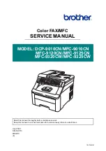
Page 1: ...03 4 Color FAX MFC SERVICE MANUAL MODEL DCP 9010CN MFC 9010CN MFC 9120CN MFC 9125CN MFC 9320CW MFC 9325CW Read this manual thoroughly before maintenance work Keep this manual in a convenient place for quick and easy reference at all times ...

Page 2: ...x and MetaFrame are registered trademarks of Citrix Systems Inc in the United States Intel Intel Xeon and Pentium are trademarks or registered trademarks of Intel Corporation AMD AMD Athlon AMD Opteron and combinations thereof are trademarks of Advanced Micro Devices Inc PictBridge is a trademark Each company whose software title is mentioned in this manual has a Software License Agreement specifi...

Page 3: ...nction of the machine will display if any error or malfunction occurs If any error message appears refer to this chapter to find which parts should be checked or replaced The latter half of this chapter provides sample problems that could occur in the main sections of the machine and related troubleshooting procedures CHAPTER 4 PERIODICAL MAINTENANCE Details of consumable parts and periodical main...

Page 4: ...e connections of the PCBs APPENDIX 1 WORKER SWITCH WSW Describes the functions of the worker switches APPENDIX 2 DELETION OF USER SETTING INFORMATION etc Provides instructions on how to delete user setting information etc stored in the machine APPENDIX 3 SERIAL NUMBERING SYSTEM APPENDIX 4 SCREW CATALOGUE APPENDIX 5 REFERENCES APPENDIX 6 GLOSSARY Information in this manual is subject to change due ...

Page 5: ...llowing interface cable A USB cable The cable must not be more than 2 meters long EU Directive 2002 96 EC and EN50419 European Union only This equipment is marked with the recycling symbol below It means that at the end of the life of the equipment you must dispose of it separately at an appropriate collection point and not place it in the normal domestic unsorted waste stream This will benefit th...

Page 6: ...e harmful interference to radio or television reception which can be determined by turning the equipment off and on the user is encouraged to try to correct the interference by one or more of the following measures Reorient or relocate the receiving antenna Increase the separation between the equipment and receiver Connect the equipment into an outlet on a circuit different from that to which the ...

Page 7: ...ible personal injury Electrical Hazard icons alert you to a possible electrical shock Hot Surface icons warn you not to touch machine parts that are hot Cautions specify procedures you must follow or avoid to prevent possible damage to the machine or other objects Note Notes tell you useful tips when servicing the machine Memo Memo tells you bits of knowledge to help understand the machine ...

Page 8: ...machine or replace parts make sure that you have turned off the power switch and unplugged the machine from the AC power outlet DO NOT handle the plug with wet hands Doing this might cause an electrical shock The fuser unit becomes extremely hot during operation Wait until it has cooled down sufficiently before replacing consumable items DO NOT remove or damage the caution label located on or arou...

Page 9: ...o prevent injuries be careful not to put your hands on the edge of the machine under the document cover as shown in the illustration To prevent injuries be careful not to put your fingers in the areas shown in the illustrations ...

Page 10: ...side the machine immediately turn off the power switch and unplug the machine from the AC power outlet This machine is heavy and weighs approximately 22 9 kg 50 5 lb To prevent injuries when moving or lifting this machine make sure to use at least two people Be careful not to pinch your fingers when you set the machine back down CAUTION Lightning and power surges can damage this product We recomme...

Page 11: ...Confidential CHAPTER 1 SPECIFICATIONS ...

Page 12: ...ST 1 2 2 1 General 1 2 2 2 Network Connectivity 1 11 2 3 Service Information 1 17 2 4 Consumables 1 18 2 5 Paper 1 19 2 5 1 Paper handling 1 19 2 5 2 Media specifications 1 19 2 5 3 Type and size of paper 1 20 2 6 Printable Area 1 21 2 7 Print Speeds with Various Settings 1 29 2 8 Telephone 1 30 2 9 FAX 1 32 2 10 List Report 1 36 2 11 Copy 1 37 2 12 Scanner 1 38 2 13 USB Direct Interface 1 40 ...

Page 13: ... PCB ASSY Engine PCB ASSY Access cover Side cover L ASSY Drum develop Front cover ASSY Toner New sensor ADF unit Side frame L Registration sensor Paper tray Top cover arm R Top cover arm L LED head control PCB ASSY drive unit PCB ASSY holder ASSY Main fan ASSY LV fan ASSY PCB ASSY power supply PCB ASSY Document scanner unit Panel unit Joint cover sub ASSY Front cover NCU PCB ASSY Speaker unit top ...

Page 14: ... Monochrome Full Color Up to 16 16 ppm A4 size Up to 17 17 ppm Letter size When loading A4 or Letter size paper from the paper tray Duplex N A Warm up time From Sleep Mode Less than 27 seconds From Power OFF ON Less than 37 second With standard 64 MB RAM 23 C 73 4 F First print time 1 Monochrome Less than 15 seconds Full Color Less than 16 seconds CPU 300 MHz Memory Standard 64 MB Option 1 DIMM sl...

Page 15: ...int speed One side Monochrome Full Color Up to 18 18 ppm A4 size Up to 19 19 ppm Letter size When loading A4 or Letter size paper from the paper tray Duplex N A Warm up time From Sleep Mode Less than 27 seconds From Power OFF ON Less than 37 second With standard 64 MB RAM 23 C 73 4 F First print time 2 Monochrome Less than 15 seconds Full Color Less than 16 seconds CPU 300 MHz Memory Standard 64 M...

Page 16: ...x 2 lines LCD dimension W x L 5 x 1 05 cm 1 85 x 0 43 inch LCD backlight Yes Green LED Error Orange Data Green Mode key Fax Copy Scan Blue FAX model only Security function lock N A Yes Model MFC9125CN MFC9325CW Noise level Sound pressure Printing 53 dB A Ready 30 dB A Sound power Printing LWAd 6 5 Bell A Ready LWAd 4 8 Bell A Environment Temperature Operating 10 to 32 5 C 50 to 90 5 F Non operatin...

Page 17: ...ndows Server 2003 x64 Edition Windows XP Professional x64 Edition Windows Server 2003 Windows XP Home Edition Professional Windows 2000 Professional Macintosh Macintosh Printer Driver for Mac OS X 10 3 9 or greater BR Script 3 PPD file for Mac OS X 10 3 9 or greater Linux 3 Linux printer driver for CUPS printing system x86 x64 environment Linux printer driver for LPD LPRng printing system x86 x64 ...

Page 18: ...indows XP Professional x64 Edition Windows Vista Windows 7 Windows Server 2003 Windows Server 2003 x64 Edition Windows Server 2008 Windows Server 2008 R2 Edition Macintosh Macintosh Printer Driver for Mac OS X 10 4 11 10 5 x 10 6 x BR Script 3 PPD file for Mac OS X 10 4 11 10 5 x 10 6 x Linux 6 Linux printer driver for CUPS printing system x86 x64 environment Linux printer driver for LPD LPRng pri...

Page 19: ... only Linux N A Model DCP9010CN MFC9010CN MFC9120CN MFC9320CW Windows BRAdmin Light Web Based Management BRAdmin Professional 3 Web BRAdmin BRAdmin Light Web Based Management BRAdmin Professional 3 Web BRAdmin Network Remote Setup Macintosh BRAdmin Light Web Based Management BRAdmin Light Web Based Management BRAdmin Professional 3 Linux Web Base Management Model DCP9010CN MFC9010CN MFC9120CN MFC9...

Page 20: ...er 2 Linux N A Remote setup Windows Yes Macintosh Yes Mac OS X only Linux N A Model MFC9125CN MFC9325CW Windows BRAdmin Light Web Based Management BRAdmin Professional 3 Web BRAdmin Network Remote Setup Macintosh BRAdmin Light Web Based Management Network Remote Setup Linux Web Base Management Model MFC9125CN MFC9325CW Direct Print N A PDF version 1 7 JPEG Exif JPEG PRN created by own printer driv...

Page 21: ...08 Intel Pentium 4 or equivalent 64 bit Intel 64 or AMD64 supported CPU 512 MB 2 GB 50 MB Windows Vista 10 512 MB 1 GB 500 MB Windows Server 2003 x64 Edition 64 bit Intel 64 or AMD64 supported CPU 256 MB 512MB 50 MB Windows XP Professional x64 Edition 150 MB Windows Server 2003 Intel Pentium III or equivalent 256 MB 512 MB 50 MB Windows XP Home Edition 10 Intel Pentium II or equivalent 128 MB 256 ...

Page 22: ...150 MB Windows Vista 12 Intel Pentium 4 or equivalent 64 bit Intel 64 or AMD64 supported CPU 512 MB 1 GB 500 MB Windows 7 12 Intel Pentium 4 or equivalent 64 bit Intel 64 or AMD64 supported CPU 1 GB 32 bit 2 GB 64 bit 1 GB 32 bit 2 GB 64 bit 650 MB Windows Server 2003 print only via network Intel Pentium III or equivalent 256 MB 512 MB 50 MB Windows Server 2003 x64 Edition print only via network 6...

Page 23: ...Raw Port Port9100 IPP IPPS FTP Server TELNET Server HTTP HTTPS server TFTP client and server SMTP Client APOP POP before SMTP SMTP AUTH SNMPv1 v2c v3 ICMPv6 LLTD responder Web Services Print SSL TLS CIFS client SNTP FTP client Network type Ethernet 10 100 BASE TX Auto Negotiation Network printing Windows Server 2008 Windows Vista Windows Server 2003 Windows XP and Windows 2000 TCP IP printing Mac ...

Page 24: ...ver HTTP HTTPS server TFTP client and server SMTP Client APOP POP before SMTP SMTP AUTH SNMPv1 v2c v3 ICMPv6 LLTD responder Web Services Print SSL TLS CIFS client SNTP FTP client Network type Ethernet 10 100 BASE TX Auto Negotiation Network printing Windows Server 2008 Windows Vista Windows Server 2003 Windows XP Windows 7 and Windows Server 2008 R2 TCP IP printing Mac OS X 10 4 11 10 5 x 10 6 x p...

Page 25: ...D responder Web Services Print SSL TLS CIFS client TCP IP IPv6 5 NDP RA DNS resolver mDNS LLMNR responder LPR LPD Custom Raw Port Port9100 IPP IPPS FTP Server TELNET Server HTTP HTTPS server TFTP client and server SMTP Client APOP POP before SMTP SMTP AUTH SNMPv1 v2c v3 ICMPv6 LLTD responder Web Services Print SSL TLS CIFS client Network type IEEE 802 11 b g wireless Frequency 2412 2472 MHz RF cha...

Page 26: ...ional Web BRAdmin 6 Windows Server 2008 Windows Vista Windows Server 2003 x64 Edition Windows XP Professional x64 Edition Windows Server 2003 Windows XP Home Edition Professional Edition Windows 2000 Professional Web Based Management Microsoft Internet Explorer 6 0 or greater Firefox 1 0 or greater for Windows and Safari 1 2 or greater for Macintosh are recommended BRAdmin Light Windows Server 200...

Page 27: ...ices Print SSL TLS CIFS client SNTP TCP IP IPv6 7 NDP RA DNS resolver mDNS LLMNR responder LPR LPD Custom Raw Port Port9100 IPP IPPS FTP Server TELNET Server HTTP HTTPS server TFTP client and server SMTP Client APOP POP before SMTP SMTP AUTH SNMPv1 v2c v3 ICMPv6 LLTD responder Web Services Print SSL TLS CIFS client SNTP Network type IEEE 802 11 b g wireless Frequency 2412 2472 MHz RF channels US C...

Page 28: ... Web BRAdmin 8 Windows Server 2008 Windows Vista Windows Server 2003 x64 Edition Windows XP Professional x64 Edition Windows Server 2003 Windows XP Home Edition Professional Edition Windows 7 Windows Server 2008 R2 Web Based Management Microsoft Internet Explorer 6 0 or greater Firefox 1 0 or greater for Windows and Safari 1 2 or greater for Macintosh are recommended BRAdmin Light Windows Server 2...

Page 29: ...eantime to repair 30 minutes Maximum monthly volume 25 000 pages Periodical maintenance parts As for replacement of the periodical maintenance parts refer to PERIODICAL MAINTENANCE in Chapter 4 Specifications are subject to change without notice Part Approximate life Fuser unit 50 000 pages Paper feeding kit 50 000 pages ADF unit 50 000 pages or 5 years Document scanner unit 50 000 pages or 5 year...

Page 30: ...8 Shelf life 2 years without opening 6 months after opening Drum unit Life expectancy Approximately 15 000 3 pages drum unit The life expectancy varies according to the use condition Refer to 1 4 27 Display of the machine s log Function code 80 in Chapter 7 When printing A4 Letter size paper Shelf life 2 years The shelf life of toner cartridge and drum unit is guaranteed under the normal condition...

Page 31: ...paper path Duplex N A Model All models Media type Paper tray Plain paper Thin paper Recycled paper Manual feed slot Plain paper Thin paper Thick paper Thicker paper Recycled paper Bond paper Label Envelopes Env Thin Env Thick Media weight Paper tray 60 to 105 g m2 16 to 28 lb Manual feed slot 60 to 163 g m2 16 to 43 lb ADF 64 to 90 g m2 17 to 24 lb Media size Paper tray A4 Letter B5 ISO A5 A5 Long...

Page 32: ... 105 g m2 16 to 28 lb Yes Yes Plain Paper Recycled paper Yes Yes Recycled Paper Bond paper Rough paper 60 to 163 g m2 16 to 43 lb N A Yes 60 to 163 g m2 16 to 43 lb Bond Paper Thick paper 105 to 163 g m2 28 to 43 lb N A Yes Thick Paper or Thicker Paper Labels N A Yes A4 or Letter Label Envelopes N A Yes Envelopes Env Thin Env Thick Memo Use paper that is made for plain paper copying Use paper that...

Page 33: ... below Specifications are subject to change without notice Note Therefore the machine can only print within the shaded area when you use a PCL driver Portrait A B C D E F G F G E G G Physical page Printable area Logical page B Physical page length D Maximum logical page length F Distance from edge of physical page to edge of logical page ...

Page 34: ... mm inch dots 176 6 9 2 078 250 9 8 2 952 164 6 5 1 936 250 9 8 2 952 6 01 0 24 71 0 0 0 4 23 0 17 50 B6 JIS mm inch dots 128 5 1 511 182 7 2 2 149 116 4 6 1 369 182 7 2 2 149 6 01 0 24 71 0 0 0 4 23 0 17 50 B6 ISO mm inch dots 125 4 9 1 476 176 6 9 2 078 113 4 4 1 334 176 6 9 2 078 6 01 0 24 71 0 0 0 4 23 0 17 50 Envelope Monarch mm inch dots 98 4 3 875 1 162 190 5 7 5 2 250 85 7 3 375 1 012 190 ...

Page 35: ...table area for a PCL driver Therefore the machine can only print within the shaded area when you use a PCL driver Landscape A B C D E F G F G E G G Physical page Printable area Logical page B Physical page length D Maximum logical page length F Distance from edge of physical page to edge of logical page ...

Page 36: ... B5 ISO mm inch dots 250 9 8 2 952 176 6 9 2 078 240 9 4 2 834 176 6 9 2 078 5 0 2 59 0 0 0 4 23 0 17 50 B6 JIS mm inch dots 182 7 2 2 149 128 5 1 511 172 6 8 2 031 128 5 1 511 5 0 2 59 0 0 0 4 23 0 17 50 B6 ISO mm inch dots 176 6 9 2 078 125 4 9 1 476 166 6 5 1 960 125 4 9 1 476 5 0 2 59 0 0 0 4 23 0 17 50 Envelope Monarch mm inch dots 190 5 7 5 2 250 98 4 3 875 1 162 180 3 7 1 2 130 98 4 3 875 1...

Page 37: ...the edges of the paper that cannot be printed on are shown below Specifications are subject to change without notice Note This is equivalent to the printable area for a PS driver Portrait A B C D E H Physical page Printable area B Physical page length D Maximum logical page length ...

Page 38: ... 17 50 B5 ISO mm inch dots 176 6 9 2 078 250 9 8 2 952 167 6 6 1 978 241 9 5 2 852 4 23 0 17 50 4 23 0 17 50 B6 JIS mm inch dots 128 5 1 511 182 7 2 2 149 119 4 7 1 411 173 6 8 2 049 4 23 0 17 50 4 23 0 17 50 B6 ISO mm inch dots 125 4 9 1 476 176 6 9 2 078 117 4 6 1 376 167 6 6 1 978 4 23 0 17 50 4 23 0 17 50 Envelope Monarch mm inch dots 98 4 3 875 1 162 190 5 7 5 2 250 89 9 3 54 1 062 182 7 17 2...

Page 39: ... Specifications are subject to change without notice Note This is equivalent to the printable area for a PS driver Landscape A B C D H E Physical page Printable area B Physical page length D Maximum logical page length ...

Page 40: ... 17 50 B5 ISO mm inch dots 250 9 8 2 952 176 6 9 2 078 241 9 5 2 852 167 6 6 1 978 4 23 0 17 50 4 23 0 17 50 B6 JIS mm inch dots 182 7 2 2 149 128 5 1 511 173 6 8 2 049 119 4 7 1 411 4 23 0 17 50 4 23 0 17 50 B6 ISO mm inch dots 176 6 9 2 078 125 4 9 1 476 167 6 6 1 978 117 4 6 1 376 4 23 0 17 50 4 23 0 17 50 Envelope Monarch mm inch dots 190 5 7 5 2 250 98 4 3 875 1 162 182 7 17 2 150 89 9 3 54 1...

Page 41: ... to change without notice Media type setting Print speed Plain paper Recycled paper DCP9010CN MFC9010CN MFC9120CN MFC9320CW 16 17 ppm MFC9125CN MFC9325CW 18 19 ppm Thick paper Envelope Envelope thin Label 8 ppm Thicker paper Bond paper Envelope thick 4 ppm Media type setting Print speed Plain paper Recycled paper DCP9010CN MFC9010CN MFC9120CN MFC9320CW 17 ppm MFC9125CN MFC9325CW 19 ppm Thick paper...

Page 42: ...eaker volume N A Yes 3 steps OFF Beeper volume N A Yes 3 steps OFF Ring volume N A Yes 3 steps OFF One touch dial N A 8 4 x 2 locations Speed dialing N A 200 locations Figures of One touch Speed dialing N A 20 digits Registerable number of characters N A 15 characters China 10 characters Group dial N A Yes Up to 20 groups Telephone Index N A Yes button Caller ID N A Yes Call waiting caller ID N A ...

Page 43: ...usic on hold N A Handset volume N A Speaker volume Yes 3 steps OFF Beeper volume Yes 3 steps OFF Ring volume Yes 3 steps OFF One touch dial 8 4 x 2 locations Speed dialing 200 locations Figures of One touch Speed dialing 20 digits Registerable number of characters 15 characters Group dial Yes Up to 20 groups Telephone Index Yes button Caller ID Yes Call waiting caller ID N A Distinctive ringing Ye...

Page 44: ...es Not available for saving the data into the Memory Fax Tel switch N A Yes Superfine N A Yes TX RX Grayscale N A 8 bit 256 Contrast N A Yes Auto Light Dark Smoothing N A Dual access 1 N A Yes Remote activate N A Yes Station ID N A Yes 20 digits 20 characters Remote maintenance N A Remote access N A Yes FAX retrieval N A Yes Paging 1 N A USA Canada Yes Europe N A Internet FAX ITU T 37 simple mode ...

Page 45: ...es Brother 1 Chart Standard Resolution JBIG ECM N A Yes Error Re Transmis sion 2 N A Yes Broadcasting 2 N A Yes 258 locations Manual broadcasting 2 N A Yes 50 locations Fax forwarding 2 N A Yes Fax forwarding broadcast 2 N A Yes 207 locations Duplex Fax sending 2 N A Dial restriction N A Yes Receiving Easy receive Fax detect N A Yes Polling receive N A Yes EUR Secure Polling Auto reduction N A Yes...

Page 46: ...t available for saving the data into the Memory Fax Tel switch Yes Superfine Yes TX RX Grayscale 8 bit 256 Contrast Yes Auto Light Dark Smoothing N A Dual access 3 Yes Remote activate Yes Station ID Yes 20 digits 20 characters Remote maintenance N A Remote access Yes FAX retrieval Yes Paging 3 USA Canada Yes Australia New Zealand N A Internet FAX ITU T 37 simple mode Yes Download only Sending Dela...

Page 47: ...to 600 pages Brother 1 Chart Standard Resolution JBIG ECM Yes Error Re Transmis sion 4 Yes Broadcasting 4 Yes 258 locations Manual broadcasting 4 Yes 50 locations Fax forwarding 4 Yes Fax forwarding broadcast 4 Yes 207 locations Duplex Fax sending 4 N A Dial restriction Yes Receiving Easy receive Fax detect Yes Polling receive Yes EUR Secure Polling Auto reduction Yes Duplex Fax receiving N A Out ...

Page 48: ... A Yes Super Help list N A Yes Call back message N A Caller ID list N A Yes Tel Index list Numeric N A Yes Alphabetic N A Yes Memory status list N A System setup User setting list Yes Model MFC9125CN MFC9325CW Activity report Journal report Yes Up to 200 Transmission verification report Yes Coverpage 1 Yes Super Help list Yes Call back message N A Caller ID list Yes Tel Index list Numeric Yes Alph...

Page 49: ... Enlargement 25 400 in 1 increments Resolution dpi Maximum 600 main scanning x 600 sub scanning dpi Auto duplex copy N A Manual duplex copy N A N in 1 Yes Poster N A Image enhancement N A Model MFC9125CN MFC9325CW Copy speed simplex Monochrome Up to 18 cpm A4 size Up to 19 cpm Letter size Color First copy out time from ready mode Monochrome Less than 19 seconds 1 Color Less than 24 seconds 1 Multi...

Page 50: ...lution Optical FB Maximum scanning 1 200 main scanning x 2 400 dpi sub scanning ADF Maximum scanning 1 200 main scanning x 600 dpi sub scanning Resolution Interpolated 19 200 main scanning x 19 200 sub scanning dpi Scanning speed Monochrome 2 35 Letter 2 49 A4 seconds 1 Color 7 04 Letter 7 48 A4 seconds 1 Grayscale 256 level Color depth Int Ext 48 bit 24 bit Custom scan profile N A Yes Duplex scan...

Page 51: ...ptical FB Maximum scanning 1 200 main scanning x 2 400 dpi sub scanning ADF Maximum scanning 1 200 main scanning x 600 dpi sub scanning Resolution Interpolated 19 200 main scanning x 19 200 sub scanning dpi Scanning speed Monochrome 2 35 Letter 2 49 A4 seconds 3 Color 7 04 Letter 7 48 A4 seconds 3 Grayscale 256 level Color depth Int Ext 48 bit 24 bit Custom scan profile Yes Duplex scanning N A Sca...

Page 52: ...Bridge N A Yes Direct print N A PDF version 1 7 JPEG Exif JPEG PRN created by own printer driver TIFF scanned by Brother model XPS version 1 0 Media drive N A Model MFC9125CN MFC9325CW PictBridge N A Yes Direct print N A PDF version 1 7 JPEG Exif JPEG PRN created by own printer driver TIFF scanned by Brother model XPS version 1 0 Media drive N A ...

Page 53: ...Confidential CHAPTER 2 THEORY OF OPERATION ...

Page 54: ... the paper tray 2 11 3 3 2 Paper supply 2 12 3 3 3 Paper registration 2 13 3 3 4 Paper eject 2 14 3 3 5 Paper supply from manual feed slot and paper eject from back 2 15 3 4 Toner Cartridge 2 16 3 4 1 Type of toner cartridge 2 16 3 4 2 Life of toner cartridge 2 16 3 4 3 Method of detecting toner life 2 17 3 4 4 Relationship between toner amount and life of toner cartridge in number of rotations of...

Page 55: ...Confidential 3 7 Location of Sensors 2 30 3 8 Adjustment of Color Registration 2 34 3 8 1 Color registration error in sub main scanning direction 2 34 3 9 Adjustment of Color Density 2 34 ...

Page 56: ...ck Toner Developing block Exposure drum Cleaner block Transfer block Charging block Toner Developing block Exposure drum Cleaner block Transfer block Charging block Belt cleaner unit Fuser eject drive motor Operation block Panel LED unit USB device or Digital camera Internal RAM RAM DIMM 144 pin Wired LAN Wireless LAN module Wireless LAN model USB direct USB direct interface model USB Video contro...

Page 57: ...l Btattery FAX model Speaker CIS HVPS control PCB LV fan Main fan Toner LED PCB emission Waste toner sensor Top cover open switch Develop release sensor PCB Registration front rear sensor PCB Manual sensor PCB Panel PCB Backlight LCD Low voltage power supply PCB Registration mark relay PCB Belt thermistor Registration mark L PCB Registration mark R PCB Density sensor shutter solenoid Fuser eject d...

Page 58: ...ler ASSY Heat roller Belt unit Waste toner box Plate Paper pick up roller Separation roller Paper tray Feed roller Registration front actuator Manual paper actuator PF registration roller Registration rear actuator Supply roller Cleaner shaft Exposure drum Y Separation pad ASSY Exposure drum M Cleaner sponge Exposure drum K Develop roller Exposure drum C Pinch roller Pinch roller 2 Exit roller Fro...

Page 59: ... Pressure roller Document rear actuator Document front actuator Pressure roller Ejection roller Separation pad Separation roller CIS unit Document rear sensor Document front sensor Timing belt ADF cover open sensor Pulley ASSY Right side Left side Suction roller Paper feed roller ...

Page 60: ...ment feeder ADF The document scanner unit consists of a scanner top cover CIS unit CIS drive ASSY and scanner base Fig 2 5 Document cover ADF ADF Document cover ASSY Scanner top cover White level reference film CIS drive belt CIS idle pulley CIS rail Scanner base CIS drive ASSY CIS flat cable CIS unit Document scanner unit Scanner cover CIS motor ...

Page 61: ... device CMOS image sensor through the rod lens array and the image is generated 2 Driving of the CIS unit The CIS unit is supported by the CIS rail and assembled on the drive belt When the CIS motor is rotated counter clockwise the CIS unit on the drive belt scans the document while sliding to the right hand side In this case the CIS unit has the capacity to scan at 2 400 dpi resolution of sub sca...

Page 62: ...Then the machine starts scanning by the operation of the panel and the CIS drive mechanism is started and the scanning operation is started The motor is rotated so that its action is transferred to the drive belt through the gear train The CIS unit scans the document while sliding to the right hand side Fig 2 6 ADF unit Drive plate ASSY Motor FB FFC cable Document scanner unit Pulley ASSY CIS unit...

Page 63: ...6 mm Minimum input media size Width 147 3 mm Length 147 3 mm 1 Function of each roller Suction roller Suction roller sends the inserted document to the inside of the ADF Separation roller Separation roller separates the sent document one by one Paper feed roller Send the document Ejection roller Eject the document 2 Function of each sensor Document front sensor Detects whether the document is set ...

Page 64: ... scanning the ADF motor is rotated clockwise the suction roller draws the document and the separation roller and separation pad send a sheet of the document to the ADF one by one from the top page of the stacked documents 2 The document is passed through the paper feed roller and is passed over the CIS unit so that the document is scanned Then the document is ejected to the document cover by the e...

Page 65: ... 3 Paper Feeding Fig 2 9 Back side Front Paper tray path Manual feed slot path Paper eject function Refer to 3 3 4 Manual feed Plate up function Refer to 3 3 1 Paper pick up function Refer to 3 3 5 function Refer to 3 3 2 ...

Page 66: ... gears The force is also transmitted to the plate up plate to push up the plate Fig 2 10 When the plate is pushed up the lift arm goes down and the hook B is released The P P gear 26 sector off the hook B rotates to push down the rib of the hook A Subsequently the ratchet of the hook A for the planetary clutch ASSY deviates from the gear and the plate up plate stops its push up function Fig 2 11 T...

Page 67: ...heets or one sheet of paper from the top of the sheets in the paper tray every time it is rotated and feeds it to the separation roller Subsequently stacks of paper are caught between the separation roller and separation pad ASSY they are then separated into single sheets Fig 2 12 Paper tray Separation roller Paper pick up roller Separation pad ASSY Front face print side ...

Page 68: ...roller and the paper is fed to the belt unit The fed paper is fed to the delivery unit by the belt unit Fig 2 13 Operation of actuators Registration front actuator detects the passage of paper and the trailing edge of paper Registration rear actuator detects the timing when the leading edge of the paper passes through the PF registration roller to adjust the starting position for writing on the pa...

Page 69: ... detect that the paper does not wind around the heat roller The paper eject rear actuator detects that the paper passes through the fuser unit to detect that a paper jam does not occur between the heat roller and exit roller 1 Memo When a paper jam is detected near the paper eject front actuator and paper eject rear actuator the paper feed motor is revolved in the reverse direction to move the gea...

Page 70: ...the actuator detects that there is a sheet of paper When the manual paper actuator is turned ON pick up from the manual feed slot is given priority Power of the paper feed motor rotates the PF registration roller and a sheet of paper is picked up When making print while the back cover is open a printed sheet is ejected from the back with its print side up Fig 2 15 Manual feed slot Manual paper act...

Page 71: ...er limit of number of rotations of develop roller The upper limit of the number of rotations of the develop roller is shown in the table below The graph given in the next page shows the overview of change in the number of printable pages in the case of making prints on A4 size paper Toner cartridge Number of printable pages Starter Black 1 000 pages Yellow Magenta Cyan 1 000 pages Standard Black 2...

Page 72: ...Toner is displayed on the LCD when the toner sensor detects that usable toner in a toner cartridge is used up or when the number of rotations of the develop roller reaches its life When Replace Toner is displayed on the LCD no print can be made on this machine until the toner cartridge in question is replaced with a new one 3 4 4 Relationship between toner amount and life of toner cartridge in num...

Page 73: ...ower is turned OFF ON for every print job and color registration adjustment and developing bias adjustment are performed Average print page page job 1 2 3 4 5 6 7 8 Cartridge life Standard K 1 500 2 174 2 556 2 803 2 975 3 102 3 200 3 277 Cartridge life Standard YMC 1 000 1 449 1 704 1 869 1 983 2 068 2 133 2 185 Cartridge life Starter KYMC 700 1 014 1 193 1 308 1 388 1 448 1 493 1 529 Average pri...

Page 74: ...urns ON the new toner sensor and it is detected that a new toner cartridge is mounted If the develop drive motor further rotates the rib on the reset gear is disengaged from the reset upper lever and the new toner sensor is turned OFF For standard toner cartridge Drive of the develop drive motor rotates the reset gear and the rib on the reset gear presses the reset upper lever Consequently the new...

Page 75: ... from the printing start time to the stop time In addition the developing bias voltage of each toner cartridge is periodically corrected so as to eliminate variation in the density of the four colors When the new toner detection mechanism detects the change to a new toner cartridge the developing bias voltage is reset Fig 2 17 Note If a toner cartridge in use is replaced to a cartridge which has p...

Page 76: ...er remained 2 The developing bias voltage is reset to the initial setting once when a toner cartridge which is not brand new is inserted After resetting the developing bias voltage correction is performed so that the developing bias voltage is corrected according to the amount of toner Corresponding counter Setting value Operation Counter of toner cartridge changes 1 Page counter for each toner ca...

Page 77: ...hown However a black mix is difficult to produce and black is shown using blackcolor paint for practical purposes Using such a principle color absorbing paints are mixed to allow many colors to be shown on the surface of a sheet of paper 1 Green Blue Cyan absorbs red R light only among the three color lights and reflects green G and blue B lights and consequently the light is identified as Cyan 2 ...

Page 78: ... surface of the drum by applying LED beam Electrostatic Latent Image 3 Development Toner is adhered to the surface of the drum Visible Image 4 Transfer The toner on the surface of the exposure drum is transferred to the paper 5 Fusing The transferred toner is fused on to the paper 6 Cleaning Toner remaining on the exposure drum and belt unit is removed for recovery After these processes the image ...

Page 79: ...er beautifully on the exposure drum Ions are produced by supplying high voltage power to the corona wire The flow of the ion charge is controlled by the constant voltage of the grid approximately 700 V and electrified the exposure drum surface evenly Fig 2 21 Corona wire Ion Grid Exposure drum ...

Page 80: ...int head are arranged in a staggered pattern The lens array forms image on the exposure drum using the light emitted from the LEDs The surface potential on the exposure drum which is evenly charged is lowered by exposure and consequently image is formed Fig 2 23 Memo The focus adjustment of the distance between the LED ASSY and exposure drum is made by the lower rollers at the both ends of the LED...

Page 81: ...sure drum is adjusted to keep printing density constant Fig 2 24 Flow up of toner to the development process 1 Toner adheres to the charged develop roller 2 The thickness of the adhered toner is evened out by the blade 3 The toner adhered to the develop roller is attracted to the exposed areas of the exposure drum Fig 2 25 Charging LED beam Exposure drum 400 V 700 V 150 V Develop roller Toner Chan...

Page 82: ...he exposure drum is transferred to paper which is traveling on the feed belt Fig 2 26 Fig 2 27 Memo The four colors of toner are coated in turn on the paper to form a color First comes K then Y then M and then C Belt unit Exposure drum K Exposure drum Y Exposure drum M Exposure drum C Transfer roller Feed belt Paper Toner ...

Page 83: ... CPU detects surface temperature of the heat roller using the thermistor and turns ON OFF the halogen heater lamp to keep the temperature constant Fig 2 28 Memo Control of fusing temperature The fuser unit adjusts such temperature according to types and sizes of paper so as to keep excellent image quality Heat roller Pressure roller Fuser unit Thermistor Halogen heater lamp Thermistor ...

Page 84: ... returned toner is attracted to the belt unit by lowering the potential of the transfer roller 3 The toner attracted to the belt unit is collected by the belt cleaner below the unit and stored in the waste toner box Fig 2 29 Memo When the toner returns to the exposure drum from the drum cleaner the develop roller is separated from the exposure drum to prevent color mixture Drum cleaner Paper Belt ...

Page 85: ...e heat roller Registration front sensor Photosensor On the registration front rear sensor PCB ASSY in the paper feed unit Detects if paper from the paper tray is passing through and detects the trailing edge position of paper Registration rear sensor Photosensor On the registration front rear sensor PCB ASSY in the paper feed unit Adjusts the write start position on paper New toner sensor Photosen...

Page 86: ... R PCB ASSY in the registration sensor holder ASSY Measures color displacement R side Density sensor Photosensor On the registration mark L PCB ASSY in the registration sensor holder ASSY Measures the density of each color Develop release sensor Photosensor On the develop release sensor PCB ASSY in the side frame R Detects the distance between the develop roller and exposure drum Document front se...

Page 87: ...r PCB ASSY sensor holder Registration mark sensor L drive motor sensor Density sensor Belt thermistor Registration mark sensor R holder ASSY Paper eject guide ASSY Paper eject rear sensor Toner LED Develop release New toner sensor Drum motor Paper eject front Front Toner sensor Internal temperature origin sensor sensor Top cover open switch Back cover sensor External temperature humidity sensor Li...

Page 88: ...idential Fig 2 32 Fig 2 33 Fuser side thermistor Fuser center thermistor Fuser unit Front Front ADF unit Document front sensor Document rear sensor ADF cover open sensor ADF sensor PCB Document scanner unit ASSY ...

Page 89: ...flection rate when the test patterns pass through the sensor The displacement in the sub main scanning direction is calculated based on the distance between the patterns read by the registration mark sensor and it is corrected 3 9 Adjustment of Color Density To obtain stable print quality the density of each toner needs to be maintained at a fixed value If the density balance between the colors ca...

Page 90: ...Confidential CHAPTER 3 ERROR INDICATION AND TROUBLESHOOTING ...

Page 91: ... 1 1 Precautions 3 1 1 2 Components 3 2 1 3 Initial Check 3 3 2 ERROR INDICATIONS 3 5 2 1 Error Codes 3 5 2 2 Error Messages 3 8 2 3 Error Cause and Remedy 3 11 3 PAPER FEEDING PROBLEMS 3 57 3 1 No Feeding 3 57 3 2 Double Feeding 3 58 3 3 Paper Jam 3 58 3 4 Dirt on Paper 3 59 3 5 Wrinkles on Paper 3 60 3 6 Curl of Paper 3 60 4 PRINT IMAGE DEFECT FROM PC USB FAX RECEPTION TROUBLESHOOTING 3 61 4 1 I...

Page 92: ...ng Function does not Switch between Tone and Pulse 3 99 10 DOCUMENT FEEDING PROBLEMS 3 100 10 1 No Feeding 3 100 10 2 Double Feeding 3 100 10 3 Paper Jam 3 101 10 4 Wrinkles 3 102 11 SCANNING IMAGE DEFECT TROUBLESHOOTING 3 103 11 1 Image Defect Examples 3 103 11 2 Troubleshooting Image Defect 3 103 12 OTHERS PROBLEMS 3 106 12 1 The Machine is not Turned on or the LCD Indication does not Appear 3 1...

Page 93: ...n connecting or disconnecting cable connectors make sure that you hold the connector body and not the cables 3 Static electricity charged in your body may damage electronic parts Before handling the PCBs touch a metal portion of the machine to discharge static electricity charged in your body When transporting PCBs be sure to wrap them in conductive sheets When replacing the LED ASSY PCBs put on a...

Page 94: ...n PCB ASSY Engine PCB ASSY Access cover Side cover L ASSY Drum develop Front cover ASSY Toner New sensor ADF unit Side frame L Paper tray Top cover arm R Top cover arm L LED head control PCB ASSY drive unit PCB ASSY holder ASSY Main fan ASSY LV fan ASSY PCB ASSY power supply PCB ASSY Document scanner unit Panel unit Joint cover sub ASSY Front cover NCU PCB ASSY Speaker unit top ASSY PCB ASSY USB d...

Page 95: ... or dust 4 Keep the machine horizontal when you carry it To prevent injuries when moving or lifting this machine make sure to use at least two people Fig 3 2 Power supply 1 The AC input power supply described on the rating plate of the machine should be within 10 of the rated voltage 2 The AC input power supply is within the regulated value 3 The cables and harnesses are connected correctly 4 The ...

Page 96: ...om temperature If the drum unit is unpacked soon after it is moved from a cold place to a warm room condensation may occur inside the unit which may cause incorrect images Instruct the user to allow the unit to come to room temperature before unpacking it This will take one or two hours 2 Low temperature The motor may not drive normally under the low temperature environment This is due to there be...

Page 97: ...sity sensor error 3 18 13 Developing bias correction failure Error which cannot be recorded occurs 3 12 32 Density sensor shutter performance malfunction 3 18 33 Right color registration sensor error 3 19 14 Developing bias correction failure Toner life end 3 12 34 Left color registration sensor error 3 19 36 HVPS PCB error in ready state 3 20 15 Developing bias correction failure Incorrect measur...

Page 98: ...life end soon C 3 30 83 Drum error K 3 14 65 Toner life end soon M 3 30 84 Paper jam at the back of the machine inside 3 37 66 Toner life end soon Y 3 30 67 Toner life end soon K 3 30 87 Toner of the color which is being used reaches the end of life when implementing adjustment of color density from the control panel cover ASSY 3 31 6A Fuser unit error The center thermistor does not detect 60 C wi...

Page 99: ...E6 Write error in EEPROM 3 21 A8 Scanning color parameter matching miss 3 44 E9 Maintenance monitor error 3 52 EC Main fan error 3 52 AD DMA transfer error 3 44 ED Communication with the wireless LAN PCB cannot be established upon startup of the power supply 3 52 AF CIS home position sensor is not turned off 3 44 B0 Document scanner unit FFC detection error 3 45 EE Unavailability of communication ...

Page 100: ...r cartridge from the drum unit and install a new toner cartridge in the drum unit Put the drum unit and toner cartridge assembly back into the machine again 3 46 Cooling Down Wait for a while The temperature of the drum unit or toner cartridge is too hot 3 32 Comm Error Poor telephone line quality caused a communication error 3 88 Connection Fail You tried to poll a fax machine that is not in poll...

Page 101: ...ou print the secure data press Job Cancel button and delete the previously stored data Except in the case of printing secure data and add more memory 3 47 Print Unable Turn off the machine Wait a few seconds and turn it on again 3 14 I 3 53 Protected Device USB direct interface model only The protect switch of the USB flash memory drive is on 3 48 3 56 Registration Scroll message Registration fail...

Page 102: ...ol panel cover ASSY 3 35 3 39 Small paper Open the back cover back output tray to let the printed paper out on the back output tray and then press Start Black button 3 27 Toner Error Dismount the drum unit of the color displayed on the LCD or all the drum units and then take out the toner cartridge from the drum unit s Put the toner cartridge back to the drum unit s and remount the drum unit s to ...

Page 103: ...used reached the end of life User Check Replace the toner cartridge of the color displayed on the LCD Error code 12 Color registration adjustment failure Incorrect measurement value of color registration adjustment User Check Replace the belt unit with a new one Replace the waste toner box with a new one Step Cause Remedy 1 Main PCB failure Replace the main PCB ASSY TONER EMPTY Step Cause Remedy 1...

Page 104: ... Cause Remedy 1 Registration mark L PCB ASSY failure Replace the registration sensor holder ASSY 2 HVPS control PCB failure Replace the HVPS control PCB ASSY 3 High voltage power supply PCB failure Replace the high voltage power supply PCB ASSY 4 Main PCB failure Replace the main PCB ASSY Step Cause Remedy 1 Main PCB failure Replace the main PCB ASSY Step Cause Remedy 1 Registration mark L PCB ASS...

Page 105: ...ck Replace the belt unit with a new one Replace the waste toner box with a new one Step Cause Remedy 1 Registration mark L PCB ASSY failure Replace the registration sensor holder ASSY 2 Main PCB failure Replace the main PCB ASSY Step Cause Remedy 1 Main PCB failure Replace the main PCB ASSY Step Cause Remedy 1 Registration mark L PCB ASSY failure Replace the registration sensor holder ASSY 2 HVPS ...

Page 106: ...rformance of the drum unit cannot be maintained and the print quality is deteriorated and therefore the use of the drum is stopped User Check Replace the drum unit of the appropriate color with a new one After replacing the drum unit with a new one reset the counter using the control panel cover ASSY on the machine Refer to 2 1 3 Resetting the life counter of the drum unit in Chapter 7 Print Unabl...

Page 107: ...failure of each LED ASSY Check the FFC connection of the appropriate color and reconnect it 2 LED head control PCB failure Replace the LED head control PCB ASSY 3 Failure of each LED ASSY Replace the LED ASSY of the appropriate color 4 Main PCB failure Replace the main PCB ASSY 5 Low voltage power supply PCB failure Replace the low voltage power supply PCB ASSY Print Unable 24 Turn the power off a...

Page 108: ...Turn the power off and then back on again Print Unable 26 Turn the power off and then back on again Print Unable 28 Turn the power off and then back on again Print Unable 29 Turn the power off and then back on again Step Cause Remedy 1 Harness connection failure of motor Check the harness connection of the appropriate motor and reconnect it 2 Motor failure Replace the appropriate motor 3 Engine PC...

Page 109: ... PCB failure Replace the engine PCB ASSY 4 HVPS control PCB failure Replace the HVPS control PCB ASSY 5 Main PCB failure Replace the main PCB ASSY Print Unable 2C Turn the power off and then back on again Print Unable 2D Turn the power off and then back on again Print Unable 2E Turn the power off and then back on again Print Unable 2F Turn the power off and then back on again Step Cause Remedy 1 T...

Page 110: ...Step Cause Remedy 1 Harness connection failure of registration mark L PCB ASSY Check the harness connection between the registration mark L PCB ASSY and registration mark relay PCB ASSY and the one between the registration mark relay PCB ASSY and engine PCB ASSY Then reconnect them 2 Harness connection failure of density sensor shutter solenoid Check the harness connection of the density sensor sh...

Page 111: ...rint Unable 33 Turn the power off and then back on again Print Unable 34 Turn the power off and then back on again Step Cause Remedy 1 Harness connection failure of registration mark PCB ASSY Check the harness connection of the registration mark PCB ASSY and reconnect it 2 Registration mark PCB failure Check the performance of the registration mark sensor following the procedure described in Funct...

Page 112: ...rodes of the drum unit and main body Refer to Fig 3 3 P3 33 and Fig 3 6 P3 34 2 Harness connection failure of high voltage power supply PCB ASSY Check the harness connection between the high voltage power supply PCB ASSY and engine PCB ASSY and the one between the high voltage power supply PCB ASSY and main PCB ASSY Then reconnect them 3 HVPS control PCB failure Replace the HVPS control PCB ASSY 4...

Page 113: ...PCB failure Replace the HVPS control PCB ASSY 2 Main PCB failure Replace the main PCB ASSY Print Unable 3A Turn the power off and then back on again Step Cause Remedy 1 Harness connection failure of engine PCB ASSY Check the harness connection between the main PCB ASSY and engine PCB ASSY and reconnect it 2 Engine PCB failure Replace the engine PCB ASSY 3 Main PCB failure Replace the main PCB ASSY...

Page 114: ...Check the harness connection between the HVPS control PCB ASSY and main PCB ASSY and reconnect it 3 HVPS control PCB failure Replace the HVPS control PCB ASSY 4 High voltage power supply PCB failure Replace the high voltage power supply PCB ASSY 5 Main PCB failure Replace the main PCB ASSY Print Unable 43 Turn the power off and then back on again Step Cause Remedy 1 Harness connection failure betw...

Page 115: ...r ASSY on the machine Refer to 2 1 3 Resetting the life counter of the drum unit in Chapter 7 No Toner Open the Top Cover then install Toner Cartridge Black K No Toner Open the Top Cover then install Toner Cartridge Yellow Y No Toner Open the Top Cover then install Toner Cartridge Magenta M No Toner Open the Top Cover then install Toner Cartridge Cyan C Step Cause Remedy 1 Harness connection failu...

Page 116: ...aper feeding kit is at the end of life The counter value of the paper feeding kit reaches the end of life Error code 54 Fuse unit is at the end of life The counter value of the fuser unit reaches the end of life Drum End Soon K Drum End Soon Y Drum End Soon M Drum End Soon C Drums End Soon Replace PF Kit1 Step Cause Remedy 1 Paper feeding kit worn out Replace the paper feeding kit Replace Fuser St...

Page 117: ...in the specified time Error code 6C Fuser unit error The center thermistor detects higher temperature than the specified value Refer to the next page for remedy Cover is Open Close the Fuser Cover which can be found behind the Back Cover of the machine Step Cause Remedy 1 Paper eject front actuator catching on some position Correct catching of the paper eject front actuator 2 Eject front sensor PC...

Page 118: ... off and then back on again Print Unable 78 Turn the power off and then back on again Step Cause Remedy 1 Harness connection failure between fuser unit connector and eject front sensor PCB ASSY Check the harness connection between the fuser unit connector and eject front sensor PCB ASSY and reconnect it 2 Harness connection failure between eject front sensor PCB ASSY and main PCB ASSY Check the ha...

Page 119: ...aper Error code 5D The belt unit will reach the end of life soon The belt unit counter value reaches 90 of life User Check Prepare a new belt unit Error code 5E The belt unit is at the end of life The belt unit counter value reaches the end of life User Check Replace the belt unit with a new one After replacing the belt unit reset the counter using the control panel cover ASSY on the machine Refer...

Page 120: ...ror code F2 Step Cause Remedy 1 Harness connection failure of waste toner sensor Check the harness connection of the waste toner sensor and reconnect it 2 Waste toner sensor failure Check the sensor performance following the procedure described in Function code 32 If any problem occurs replace the waste toner sensor 3 HVPS control PCB failure Replace the HVPS control PCB ASSY 4 Main PCB failure Re...

Page 121: ...r Cartridge Magenta M Replace Toner Open the Top Cover replace Toner Cartridge Yellow Y Replace Toner Open the Top Cover replace Toner Cartridge Black K Step Cause Remedy 1 HVPS control PCB failure Replace the HVPS control PCB ASSY 2 Engine PCB failure Replace the engine PCB ASSY 3 Main PCB failure Replace the main PCB ASSY 4 Harness connection failure of toner new sensor PCB ASSY Check the sensor...

Page 122: ... ASSY Check the sensor performance following the procedure described in Function code 32 If any problem occurs check the harness connection of the toner new sensor PCB ASSY then reconnect it 5 Toner new sensor PCB failure Replace the toner new sensor PCB ASSY Print Unable 70 Turn the power off and then back on again Step Cause Remedy 1 Harness connection failure of fuser eject drive motor Check th...

Page 123: ...Y The counter value of the develop roller reaches the end of life or the toner sensor detects toner empty User Check If any of the toner cartridges reaches the end of life replace it with a new one Print Unable 73 Turn the power off and then back on again Step Cause Remedy 1 Harness connection failure of LED head control PCB ASSY Check the harness connection between the main PCB ASSY and LED head ...

Page 124: ... corona wire in the drum unit Replace the drum unit of the appropriate color with a new one Cooling Down Drum Error Slide the Green tab on Drum Unit Black K Cyan C Magenta M Yellow Y Refer to the User s Guide Step Cause Remedy 1 Dirt or dust on drum unit electrodes Clean the electrodes of the drum unit belt unit and main body Refer to Fig 3 3 Fig 3 4 next page and Fig 3 6 P3 34 2 HVPS control PCB ...

Page 125: ...3 33 Confidential Electrodes location of the drum unit and toner cartridge Fig 3 3 Electrodes location of the belt unit Fig 3 4 Black only ...

Page 126: ...on of main body Fig 3 6 How to clean the electrodes Turn off the power switch Unplug the machine from the AC power outlet and leave the machine for a few minutes Then wipe the electrodes above carefully with a dry lint free cloth Be careful not to change the shapes of the electrodes ...

Page 127: ... paper is smaller 10 mm than the Letter size in Fax List Report User Check Set the defined size paper Size mismatch Fax received Set correct paper size in menu Size mismatch Reload correct paper Step Cause Remedy 1 Registration front actuator catching on some position Correct catching of the registration front actuator 2 Main PCB failure Replace the main PCB ASSY ...

Page 128: ...re installed in the correct order of colors Calibrate Calibration failed See Troubleshooting chapter in User s Guide Calibrate Calibration failed Press Start and try again Step Cause Remedy 1 Density sensor shutter catching on some position Correct catching of the density sensor shutter 2 Harness connection failure of registration mark L PCB ASSY Check the harness connection of the registration ma...

Page 129: ...eck the harness connections of the registration front rear sensor PCB ASSY and eject front sensor PCB ASSY and reconnect them 2 Registration rear actuator or paper eject front actuator catching on some position Correct catching of the registration rear actuator or paper eject front actuator 3 Eject front sensor PCB failure Error code 84 Check the sensor performance following the procedure describe...

Page 130: ...ar sensor PCB ASSY and reconnect it 2 Paper feeding kit worn out Replace the paper feeding kit 3 Registration front rear sensor PCB failure Check the sensor performance following the procedure described in Function code 32 If any problem occurs replace the registration front rear sensor PCB ASSY 4 HVPS control PCB failure Replace the HVPS control PCB ASSY 5 Main PCB failure Replace the main PCB AS...

Page 131: ...size of the tray and that of the data are not matched User Check Check the paper size to be supported and load the appropriate size of paper Registration Registration failed Press Start and try again Registration Registration failed See Troubleshooting chapter in User s Guide Registration Registration failed See Troubleshooting chapter in User s Guide Step Cause Remedy 1 Harness connection failure...

Page 132: ...ze paper then press Start Step Cause Remedy 1 Lift arm and roller holder ASSY not assembled correctly Be sure to put the boss of the roller holder ASSY into the hole on the lift arm securely 2 Harness connection failure of registration front rear sensor PCB ASSY Check the harness connection of the registration front rear sensor PCB ASSY and reconnect it 3 Plate up function malfunction Replace the ...

Page 133: ...sert the blank paper into the Manual feed slot Step Cause Remedy 1 Harness connection failure of manual sensor PCB ASSY Check the harness connection of the manual sensor PCB ASSY and reconnect it 2 Manual sensor failure Check the sensor performance following the procedure described in Function code 32 If any problem occurs replace the manual sensor PCB ASSY 3 Registration front rear sensor PCB fai...

Page 134: ...nnection of the top cover switch ASSY and reconnect it 2 The member to press the top cover switch at the right side of the inside of the top cover is broken Replace the top cover sub ASSY 3 HVPS control PCB failure Replace the HVPS control PCB ASSY 4 Main PCB failure Replace the main PCB ASSY Document Jam Clear the scanner jam then press the Stop Key Document Jam Clear the scanner jam then press t...

Page 135: ...open sensor actuator catching on some position Correct catching of the ADF cover open sensor actuator 2 Harness connection failure of ADF sensor PCB Check the harness connection of the ADF sensor PCB and reconnect it 3 ADF cover is changed in shape or cracked Replace the ADF cover ASSY 4 ADF sensor PCB failure Replace the ADF sensor PCB ASSY 5 Main PCB failure Replace the main PCB ASSY Scan Unable...

Page 136: ...e Step Cause Remedy 1 Document scanner unit failure Replace the document scanner unit 2 Main PCB failure Replace the main PCB ASSY Scan Unable AD Remove the original document Turn the power off then on again Step Cause Remedy 1 Document scanner unit failure Replace the document scanner unit 2 Main PCB failure Replace the main PCB ASSY Scan Unable AF See Troubleshooting and routine maintenance chap...

Page 137: ...igh side This error is indicated on the LCD in the maintenance mode Error code B8 A D converter standard voltage failure at Low side This error is indicated on the LCD in the maintenance mode Error code B9 Scanning light adjustment error This error is indicated on the LCD in the maintenance mode Refer to the next page for remedy Scanner Error Step Cause Remedy 1 Incomplete insertion of the harness...

Page 138: ...r sensor sticks at ON User Check Install the toner cartridges into the machine properly Scanner Error Scanner Error Step Cause Remedy 1 Document scanner unit failure Replace the document scanner unit 2 Main PCB failure Replace the main PCB ASSY Cartridge Error Put the Black K Toner Cartridge back in Cartridge Error Put the Yellow Y Toner Cartridge back in Cartridge Error Put the Magenta M Toner Ca...

Page 139: ...ess connection of the develop release motor and reconnect it 2 Harness connection failure of develop release sensor PCB ASSY Check the harness connection of the develop release sensor PCB ASSY and reconnect it 3 Develop release motor failure Replace the develop release motor ASSY 4 Develop release sensor PCB failure Replace the develop release sensor PCB ASSY 5 Engine PCB failure Replace the engin...

Page 140: ... while Replace the USB device with other one DIMM Error Make sure that the DIMM is inserted correctly Unusable Device Remove the Device Turn the power off and back on again Step Cause Remedy 1 Harness connection failure of USB direct interface relay PCB ASSY Check the harness connection of the USB direct interface relay PCB ASSY and reconnect it 2 USB direct interface relay PCB failure Replace the...

Page 141: ...on failure of registration mark L PCB ASSY Check the harness connection of the registration mark L PCB ASSY and reconnect it 2 Harness connection failure of shutter solenoid of the density sensor Check the harness connection of shutter solenoid of the density sensor and reconnect it 3 Engine PCB failure Replace the engine PCB ASSY 4 Main PCB failure Replace the main PCB ASSY 5 Registration mark L ...

Page 142: ...Harness connection failure of waste toner sensor Check the harness connection of the waste toner sensor and reconnect it 2 Waste toner sensor failure Check the sensor performance following the procedure described in Function code 32 If any problem occurs replace the waste toner sensor 3 HVPS control PCB failure Replace the HVPS control PCB ASSY 4 Main PCB failure Replace the main PCB ASSY Machine ...

Page 143: ... E1 Turn off and on Step Cause Remedy 1 Main PCB failure Replace the main PCB ASSY Print Unable E2 Turn the power off and then back on again Step Cause Remedy 1 Fuser unit failure Replace the fuser unit 2 Eject front sensor PCB failure Replace the eject front sensor PCB ASSY 3 Main PCB failure Replace the main PCB ASSY Print Unable E3 Turn the power off and then back on again Step Cause Remedy 1 D...

Page 144: ...ace the main PCB ASSY Print Unable EC Turn the power off and then back on again Step Cause Remedy 1 Connection failure of main fan connector Check the connection of the main fan connector and reconnect it 2 Main fan failure Replace the main fan ASSY 3 HVPS control PCB failure Replace the HVPS control PCB ASSY 4 High voltage power supply PCB failure Replace the high voltage power supply PCB ASSY 5 ...

Page 145: ...ltage discharge due to reaching the life of the cleaning roller User Check Prepare a new waste toner box Print Unable EE Turn the power off and then back on again Step Cause Remedy 1 Wireless LAN PCB failure Replace the wireless LAN PCB ASSY 2 Main PCB failure Replace the main PCB ASSY Print Unable EF Turn the power off and then back on again Step Cause Remedy 1 Low voltage power supply PCB failur...

Page 146: ...x Refer to the User s Guide for instructions Note The same message appears in the case of the error code CF Step Cause Remedy 1 HVPS control PCB failure Replace the HVPS control PCB ASSY 2 Engine PCB failure Replace the engine PCB ASSY Machine Error F8 Step Cause Remedy 1 Harness connection failure of battery Check the connection of the battery connector and reconnect it 2 Battery failure Replace ...

Page 147: ...Toner Cartridge Cyan C No Toner Open the Top Cover then install Toner Cartridge Magenta M No Toner Open the Top Cover then install Toner Cartridge Yellow Y Step Cause Remedy 1 Bend of electrode contact of main body Correct the bend of the electrode contact of the main body 2 Dirt on electrodes of main body Clean the electrodes of the main body Refer to Fig 3 6 P3 34 3 HVPS control PCB failure Repl...

Page 148: ...ion failure of registration mark L PCB ASSY Check the harness connection of the registration mark L PCB ASSY and reconnect it 3 Registration mark relay PCB failure Replace the registration mark relay PCB ASSY 4 Main PCB failure Replace the main PCB ASSY 5 Registration mark L PCB failure Replace the registration sensor holder ASSY Unusable Device Remove the Device Turn the power off and back on aga...

Page 149: ...e gear damaged Is the plate gear damaged Yes Replace the paper tray 3 Registration front actuator malfunction Does the registration front actuator move smoothly No Re assemble the registration front actuator 4 Disconnection of the pick up solenoid harness Is the harness of the pick up solenoid disconnected Yes Reconnect the harness of the pick up solenoid 5 Registration front rear sensor PCB failu...

Page 150: ... out Is the surface of the separation pad or separation roller worn out Yes Replace the paper feeding kit Step Cause Check Result Remedy 1 Foreign object around front section Is there a foreign object around the front section Yes Remove the foreign object 2 Belt unit malfunction Does the belt unit move correctly No Replace the belt unit 3 Registration front actuator catching on some position Does ...

Page 151: ...ar actuator move smoothly Is it damaged No Replace the fuser unit 5 Eject front sensor PCB failure Is the problem solved by replacing the eject front sensor PCB ASSY Yes Replace the eject front sensor PCB ASSY 6 Eject rear sensor PCB failure Is the problem solved by replacing the eject rear sensor PCB ASSY Yes Replace the eject rear sensor PCB ASSY Step Cause Check Result Remedy 1 Fuser unit dirty...

Page 152: ...use Check Result Remedy 1 Fuser unit failure Do wrinkles on the paper disappear after replacing the fuser unit with a new one Yes Replace the fuser unit User Check Change the curl improvement mode setting of the driver Switch the delivery roller switch lever Note Be sure not set the curl improvement mode of the driver and switch to the delivery roller switch lever at the same time because it might...

Page 153: ...ely blank Image distortion All one color Dirt on the back of paper Vertical streaks Vertical streaks in a light background Horizontal stripes White vertical streaks on one color image Poor fixing Faint print White spots on one color image One color spots or dirt One color band Downward fogging of solid color Horizontal lines Vertical streaks in a dark background Ghost Color misregistration Fogging...

Page 154: ... mode Replace the toner cartridge or drum unit with a new one Adjust the color density from the control panel cover ASSY Leave the machine for a while as the power remains ON Step Cause Check Result Remedy 1 HVPS control PCB failure Is the problem solved after replacing the HVPS control PCB ASSY Yes Replace the HVPS control PCB ASSY 2 High voltage power supply PCB failure Is the problem solved aft...

Page 155: ...Fig 3 6 P3 34 3 Dirt on belt unit electrode Are the electrodes on the belt unit of the appropriate color and machine body dirty Yes Clean both electrodes Refer to Fig 3 4 P3 33 and Fig 3 6 P3 34 4 Dirt on LED array Is the LED array of the appropriate color dirty Yes Wipe the dirt off with a clean soft and lint free cloth 5 Lifting of LED ASSY Is printing of the LED ASSY test pattern correctly done...

Page 156: ...control PCB ASSY Yes Replace the LED head control PCB ASSY 11 Main PCB failure Is the problem solved after replacing the main PCB ASSY Yes Replace the main PCB ASSY Step Cause Check Result Remedy 1 Registration rear actuator catching on some position Does the registration rear actuator move smoothly No Correct catching of the registration rear actuator 2 HVPS control PCB failure Is the problem sol...

Page 157: ...d after replacing the HVPS control PCB ASSY Yes Replace the HVPS control PCB ASSY 4 High voltage power supply PCB failure Is the problem solved after replacing the high voltage power supply PCB ASSY Yes Replace the high voltage power supply PCB ASSY 5 Engine PCB failure Is the problem solved after replacing the engine PCB ASSY Yes Replace the engine PCB ASSY 6 Main PCB failure Is the problem solve...

Page 158: ... failure Is the problem solved after replacing the fuser unit Yes Replace the fuser unit 3 Low voltage power supply PCB failure Is the problem solved after replacing the low voltage power supply PCB ASSY Yes Replace the low voltage power supply PCB ASSY 4 HVPS control PCB failure Is the problem solved after replacing the HVPS control PCB ASSY Yes Replace the HVPS control PCB ASSY 5 High voltage po...

Page 159: ...ASSY Yes Replace the LED ASSY 5 HVPS control PCB failure Is the problem solved after replacing the HVPS control PCB ASSY Yes Replace the HVPS control PCB ASSY 6 High voltage power supply PCB failure Is the problem solved after replacing the high voltage power supply PCB ASSY Yes Replace the high voltage power supply PCB ASSY 7 LED head control PCB failure Is the problem solved after replacing the ...

Page 160: ...ontrol PCB failure Is the problem solved after replacing the HVPS control PCB ASSY Yes Replace the HVPS control PCB ASSY 4 High voltage power supply PCB failure Is the problem solved after replacing the high voltage power supply PCB ASSY Yes Replace the high voltage power supply PCB ASSY 5 LED ASSY failure Is the problem solved after replacing the LED ASSY Yes Replace the LED ASSY 6 LED head contr...

Page 161: ... the paper feed system Is the paper tray or feed system on the drum unit dirty with toner Yes Wipe dirt off 3 Waste toner sensor failure Is the waste toner box full of toner Yes Replace the waste toner sensor 4 HVPS control PCB failure Is the problem solved after replacing the HVPS control PCB ASSY Yes Replace the HVPS control PCB ASSY 5 High voltage power supply PCB failure Is the problem solved ...

Page 162: ...ner Yes Wipe dirt off 2 Exposure drum dirty Is there vertical dirt with toner on the surface of the exposure drum Yes Clean the drum unit 3 Bend of tray ground spring Is the tray ground spring bent Refer to Fig 3 10 Yes Replace the paper tray 4 Scratch on the heat roller Is there a scratch on the surface of the heat roller Yes Replace the fuser unit 5 LED ASSY failure Is the problem solved after r...

Page 163: ...side of the machine and the corona wire in the drum unit Clean the LED array with a soft lint free cloth Replace the toner cartridge with a new one Memo You can check this image defect with the function code 71 Refer to 1 4 21 Color test pattern Function code 71 in Chapter 7 Step Cause Check Result Remedy 1 LED ASSY failure Is the problem solved after replacing the LED ASSY Yes Replace the LED ASS...

Page 164: ... Is the tray ground spring bent Refer to Fig 3 10 P3 70 Yes Replace the paper tray 3 Toner attached on the develop roller Are the horizontal stripes at 31 mm develop roller circumference intervals Yes This problem will disappear by printing approximate 10 pages If the same problem occurs replace the toner cartridge 4 Scratch on the heat roller Are the horizontal stripes at 78 mm heat roller circum...

Page 165: ...nvironment High temperature and high humidity or low temperature and low humidity conditions can cause this problem Damp wet paper might be used Try to change to freshly unpacked paper Replace the drum unit with a new one Step Cause Check Result Remedy 1 Condensation Has condensation occurred inside the machine Yes Try to print several pages or leave the machine 2 hours to allow it to reach room t...

Page 166: ...cing the high voltage power supply PCB ASSY Yes Replace the high voltage power supply PCB ASSY 3 Engine PCB failure Is the problem solved after replacing the engine PCB ASSY Yes Replace the engine PCB ASSY User Check Open and close the top cover and make print again Check that the machine is installed on a level surface Replace the toner cartridge with a new one Clean the LED array with a soft lin...

Page 167: ... or more or when the same problem occurs after feeding the drum cleaning sheet wipe off the dirt on the exposure drum with a cotton swab Refer to Drum unit cleaning in this chapter The drum unit may be damaged Replace the drum unit with a new one The belt unit may be damaged Replace the belt unit with a new one Step Cause Check Result Remedy 1 Toner cartridge failure Are the white spots at 31 mm d...

Page 168: ...manual feed slot until the front edge of the paper touches the paper feed roller Wait until the machine automatically feeds the paper When you feel the machine pull in the paper let go Fig 3 13 Note If there is any problem in the print quality be sure to clean the drum unit in accordance with Drum cleaning function of product provided below If the problem still persists be sure to clean the drum u...

Page 169: ...n so that the machine returns to the ready state 8 Repeat steps 3 to 7 two more times Note Make sure that the paper is straight and in the correct position on the manual feed slot If it is not the paper may not be fed properly resulting in a skewed printout or a paper jam Do not put more than one piece of paper in the manual feed slot at any one time as it may cause a jam If you put paper in the m...

Page 170: ... Fig 3 15 3 Turn the drum unit gear to the direction of the arrow as shown in the figure below by hand to find smears on the drum while looking at the surface of the drum 1 Fig 3 16 4 When you have found the mark on the drum that matches the print sample wipe the surface of the drum gently with a cotton swab until the dust or paper powder on the surface comes off Fig 3 17 Note We recommend that yo...

Page 171: ...ct in this chapter When the same problem occurs after feeding the drum cleaning sheet wipe off the dirt on the exposure drum with a cotton swab Refer to Drum unit cleaning in the previous pages The drum unit may be damaged Replace the drum unit with a new one The belt unit may be damaged Replace the belt unit with a new one Step Cause Check Result Remedy 1 Fuser unit failure Are the spots at 78 mm...

Page 172: ... toner cartridge with a new one Step Cause Check Result Remedy 1 HVPS control PCB failure Is the problem solved after replacing the HVPS control PCB ASSY Yes Replace the HVPS control PCB ASSY 2 High voltage power supply PCB failure Is the problem solved after replacing the high voltage power supply PCB ASSY Yes Replace the high voltage power supply PCB ASSY 3 Engine PCB failure Is the problem solv...

Page 173: ...rminal bent which is provided in the machine body Yes Correct bending of paper tray ground terminal 3 Toner attached on the develop roller Are the horizontal lines at 31 mm develop roller circumference intervals Yes This symptom might disappear after making approximate 10 prints 4 Scratch on the heat roller Are the horizontal lines at 78 mm heat roller circumference intervals Yes Replace the fuser...

Page 174: ...d after replacing the high voltage power supply PCB ASSY Yes Replace the high voltage power supply PCB ASSY 3 Engine PCB failure Is the problem solved after replacing the engine PCB ASSY Yes Replace the engine PCB ASSY User Check Implement the adjustment of color registration from the control panel cover ASSY Replace the belt unit with a new one Replace the drum unit with a new one Step Cause Chec...

Page 175: ...r new sensor PCB ASSY 2 HVPS control PCB failure Is the problem solved after replacing the HVPS control PCB ASSY Yes Replace the HVPS control PCB ASSY 3 High voltage power supply PCB failure Is the problem solved after replacing the high voltage power supply PCB ASSY Yes Replace the high voltage power supply PCB ASSY 4 Engine PCB failure Is the problem solved after replacing the engine PCB ASSY Ye...

Page 176: ...4 3 Dirt on belt unit electrode Are the electrodes on the belt unit and machine body dirty Yes Clean both electrodes Refer to Fig 3 4 P3 33 and Fig 3 6 P3 34 4 Engine PCB failure Is the problem solved after replacing the engine PCB ASSY Yes Replace the engine PCB ASSY 5 HVPS control PCB failure Is the problem solved after replacing the HVPS control PCB ASSY Yes Replace the HVPS control PCB ASSY 6 ...

Page 177: ... environment conditions such as high humidity and low humidity may cause this situation to occur Make a print on a different type of paper Replace the drum unit with a new one Replace the toner cartridge with a new one Step Cause Check Result Remedy 1 Fuser unit failure Is the problem solved after replacing the fuser unit Yes Replace the fuser unit ...

Page 178: ...ry shipment Refer to User s guide Step Cause Check Result Remedy 1 Failure inside the machine Does the machine print test pattern Check it following the procedure described in 1 4 5 Monochrome image quality test pattern Function code 09 in Chapter 7 No Identify the error type and then refer to the specified section of this chapter 2 Machine connection For Macintosh has the product ID been verified...

Page 179: ... LAN PCB and main PCB Wireless LAN model only Is the problem solved after obtaining the correct MAC address Ethernet Address Yes Obtain the MAC address Ethernet Address Refer to 2 1 Acquiring MAC Address Ethernet Address from Main PCB in Chapter 6 2 Wireless LAN PCB failure Wireless LAN model only Is the problem solved after replacing the wireless LAN PCB ASSY Yes Replace the wireless LAN PCB ASSY...

Page 180: ...nition of Error Codes on the Communications List 1 Calling Available in German models only Code 1 Code 2 Cause 10 08 Wrong number called 11 01 No dial tone detected before start of dialing 11 02 Busy tone detected before dialing 11 03 2nd dial tone not detected 11 05 No loop current detected 11 06 Busy tone detected after dialing or called 11 07 No response from the remote station in sending 11 10...

Page 181: ...e out error 20 0B CRP received 20 0C EOR and NULL received Code 1 Code 2 Cause 32 01 Remote terminal only with V 29 capability in 2 400 or 4 800 bps transmission 32 02 Remote terminal not ready for polling 32 10 Remote terminal not equipped with password function or its password switch OFF 32 11 Remote terminal not equipped with or not ready for confidential mailbox function 32 12 Remote terminal ...

Page 182: ...6 Polled while not ready 40 07 No document to send when polled 40 10 Nation code or manufacturer code not correct 40 13 Polled by any other manufacturers terminal while waiting for secure polling 40 17 Invalid resolution selected 40 20 Invalid full color mode selected Code 1 Code 2 Cause 50 01 Vertical resolution capability changed after compensation of background color Code 1 Code 2 Cause 63 01 P...

Page 183: ...l transmission speed for fallback A0 11 Receive buffer empty 5 second time out A0 12 Receive buffer full during operation except receiving into memory A0 13 Decoding error continued on 500 lines or more A0 14 Decoding error continued for 10 seconds or more A0 15 Time out 13 seconds or more for one line transmission A0 16 RTC not found or carrier OFF detected for 6 seconds A0 17 RTC found but no co...

Page 184: ...ent of FAX communication BF 02 Communication canceled by pressing the Stop Exit button after establishment of FAX communication BF 03 Transmission canceled due to a scanning error caused by no document or document feed problem in ADF scanning in real time transmission Code 1 Code 2 Cause C0 01 No common modulation mode or failed to poll C0 02 Unable to detect JM C0 03 Unable to detect CM C0 04 Una...

Page 185: ... Equipment error Code 1 Code 2 Cause E0 01 Failed to detect 1300 Hz signal in burn in operation E0 02 Failed to detect PB signals in burn in operation Code 1 Code 2 Cause FF X X Equipment error For X X refer to 2 1 Error Codes in this chapter ...

Page 186: ...ected properly No Reconnect the connector properly 3 LCD Is the problem solved after replacing the LCD Yes Replace the LCD 4 Panel PCB Is the problem solved after replacing the panel PCB ASSY Yes Replace the panel PCB ASSY 5 High voltage power supply PCB ASSY Is the problem solved after replacing the high voltage power supply PCB ASSY Yes Replace the high voltage power supply PCB ASSY 6 Low voltag...

Page 187: ...rom control panel cover ASSY and panel keys 2 Connection between main PCB and panel PCB Are the main PCB and panel PCB connected properly No Reconnect the connector properly 3 Rubber key Is the problem solved after replacing the rubber key Yes Replace the rubber Key 4 Panel PCB Is the problem solved after replacing the panel PCB ASSY Yes Replace the panel PCB ASSY 5 Main PCB Is the problem solved ...

Page 188: ...ction between main PCB and NCU PCB Are the main PCB and NCU PCB connected properly No Reconnect the connector properly 3 Connection between main PCB and panel PCB Are the main PCB and panel PCB connected properly No Reconnect the connector properly 4 Contact of rubber key Does the rubber key work correctly No Replace the rubber Key 5 NCU PCB Is the problem solved after replacing the NCU PCB ASSY Y...

Page 189: ...tween main PCB and NCU PCB Are the main PCB and NCU PCB connected properly No Reconnect the connector properly 4 Connection between main PCB and panel PCB Are the main PCB and panel PCB connected properly No Reconnect the connector properly 5 Rubber key Is the problem solved after replacing the rubber key Yes Replace the rubber Key 6 NCU PCB Is the problem solved after replacing the NCU PCB ASSY Y...

Page 190: ... ASSY 6 Main PCB Is the problem solved after replacing the main PCB ASSY Yes Replace the main PCB ASSY Step Cause Check Result Remedy 1 Connection between main PCB and speaker Are the main PCB and speaker connected properly No Reconnect the connector properly 2 Speaker Is the problem solved after replacing the speaker unit Yes Replace the speaker unit 3 Connection between main PCB and NCU PCB Are ...

Page 191: ...onnection between main PCB and NCU PCB Are the main PCB and NCU PCB connected properly No Reconnect the connector properly 2 NCU PCB Is the problem solved after replacing the NCU PCB ASSY Yes Replace the NCU PCB ASSY 3 Main PCB Is the problem solved after replacing the main PCB ASSY Yes Replace the main PCB ASSY ...

Page 192: ...e document front sensor connected securely No Reconnected the harness of the document front sensor 3 ADF motor harness connection failure Is the harness of the ADF motor connected securely No Reconnected the harness of the ADF motor 4 Document front sensor malfunction Does the document front sensor move smoothly Check it following the procedure described in Maintenance mode 32 No Replace the ADF s...

Page 193: ... some position Does the document rear sensor actuator move smoothly No Re assembly the document rear sensor actuator 3 Document rear sensor malfunction Does the document rear sensor move smoothly Check it following the procedure described in Maintenance mode 32 No Replace the ADF sensor PCB ASSY 4 Paper feed roller failure Does the paper feed roller move smoothly Is it damaged No Replace the paper...

Page 194: ...he document guide matches the document size Check whether the document does not curl Step Cause Check Result Remedy 1 Separation roller worn out Is the separation roller worn out Yes Replace the roller holder ASSY 2 Paper feed roller worn out Is the paper feed roller worn out Yes Replace the paper feed roller ASSY ...

Page 195: ...ther the setting of the contrast does not become light Step Cause Check Result Remedy 1 White level data malfunction Is the problem solved by performing the acquisition of white level data Function code 55 Yes Perform the acquisition of white level data Function code 55 2 CIS unit failure Is the problem solved after replacing the document scanner unit Yes Replace the document scanner unit 3 Main P...

Page 196: ...ed by performing the fine adjustment of scan start position Function code 54 Yes Perform the fine adjustment of scan start position Function code 54 2 CIS unit failure Is the problem solved after replacing the document scanner unit Yes Replace the document scanner unit User Check Check whether the setting of the contrast does not become dark Step Cause Check Result Remedy 1 White level data malfun...

Page 197: ...s Replace the document scanner unit 3 Main PCB failure Is the problem solved after replacing the main PCB ASSY Yes Replace the main PCB ASSY User Check Check if the ADF glass or document glass is not stained Step Cause Check Result Remedy 1 CIS unit failure Is the problem solved after replacing the document scanner unit Yes Replace the document scanner unit User Check Check if the ADF glass or doc...

Page 198: ...he LCD 4 Low voltage power supply PCB failure Is the problem solved after replacing the Low voltage power supply PCB ASSY Yes Replace the low voltage power supply PCB ASSY 5 Panel PCB failure Is the problem solved after replacing the panel PCB ASSY Yes Replace the panel PCB ASSY 6 High voltage power supply PCB failure Is the problem solved after replacing the high voltage power supply PCB ASSY Yes...

Page 199: ...PCB ASSY Yes Replace the HVPS control PCB ASSY 5 High voltage power supply PCB failure Is the problem solved after replacing the high voltage power supply PCB ASSY Yes Replace the high voltage power supply PCB ASSY 6 Low voltage power supply PCB failure Is the problem solved after replacing the low voltage power supply PCB ASSY Yes Replace the low voltage power supply PCB ASSY 7 Main PCB failure I...

Page 200: ...oner actuator of the appropriate color 2 Main PCB failure Replace the main PCB ASSY 3 Toner new sensor PCB failure Replace the toner new sensor PCB ASSY of the appropriate color Step Cause Check Result Remedy 1 Failure inside the machine Does the machine print test pattern Check it following the procedure described in 1 4 5 Monochrome image quality test pattern Function code 09 in Chapter 7 No Ide...

Page 201: ...Confidential CHAPTER 4 PERIODICAL MAINTENANCE ...

Page 202: ...pter also covers procedures for disassembling and assembling periodical maintenance parts CONTENTS 1 SAFETY PRECAUTIONS 4 1 2 CONSUMABLE PARTS 4 1 3 PERIODICAL MAINTENANCE PARTS 4 3 3 1 Periodical Maintenance Parts 4 3 3 2 Procedures to Replace Periodical Maintenance Parts 4 4 3 2 1 Fuser unit 4 5 3 2 2 Paper feeding kit 4 17 ...

Page 203: ...ely 1 000 pages When printing A4 size paper in accordance with ISO IEC 19798 Standard cartridge Approximately 2 200 pages When printing A4 size paper in accordance with ISO IEC 19798 Yellow Magenta Cyan Starter cartridge Approximately 1 000 pages When printing A4 size paper in accordance with ISO IEC 19798 Standard cartridge Approximately 1 400 pages When printing A4 size paper in accordance with ...

Page 204: ...uous printing Example Starts to print when the machine is in the Ready state If you leave the machine without printing for a long time the number of drum rotations is increasing because the developing bias voltage correction and the color registration are performed If you print one page per one job every time after leaving the machine without printing for a long time the drum unit life is shorter ...

Page 205: ...e log information display maintenance mode 80 Refer to 1 4 27 Display of the machine s log in Chapter 7 The actual number of printed page will vary depending on the type of print job or the paper to being used The figures indicated as the approximate life in the table above are worked out when printing a general business document in accordance with ISO IEC 19798 on A4 size paper Parts name LCD App...

Page 206: ...h the disassembly procedure 1 Unplug the AC cord the modular jack of the telephone line the USB cable if connected the LAN cable if connected the USB cable for PictBridge or USB flash memory drive if connected and the modular jack of the external telephone set if connected 2 Remove the Paper tray Paper tray ...

Page 207: ...installing procedure 1 Open the Back cover Fig 4 1 2 Release the Hook and remove the Back cover stopper L and R from the Main body Fig 4 2 Back cover Back side Hook Back cover stopper L Back cover stopper R Main body Back side Back cover ...

Page 208: ...cover from the Shaft at the right side of the Main body Fig 4 3 4 Remove the Back cover from the Shaft at the left of the Main body Fig 4 4 Main body Back cover Bush Bush Shaft Shaft Right side 3a 3b 3c Back side Main body Shaft Back cover Left side ...

Page 209: ...ide frame L 7 Take out the Shaft at the right side of the Fuser cover from the Bush of the LVPS cover and remove the Fuser cover Fig 4 6 Fuser cover lock lever L Fuser cover Fuser cover lock lever R 5b Back side Fuser cover lock lever L Fuser cover lock lever R 5a 5a Side frame L Bush Shaft at the left side LVPS cover Notch on the bush Fuser cover Shaft at the right side 7a 7b Back side ...

Page 210: ... remove the Fuser cover L from the Fuser unit Fig 4 7 9 Remove the Taptite bind B M3x12 screw and then remove the Fuser cover R from the Fuser unit Fig 4 8 Fuser unit Fuser cover L Taptite bind B M3x12 Back side Taptite bind B M3x12 Fuser unit Fuser cover R Back side ...

Page 211: ...from the Eject front sensor PCB ASSY Fig 4 9 11 Disconnect the two Electrode terminals from the Fuser unit Fig 4 10 Connector CN1 Eject front sensor PCB ASSY CN1 CN3 Connector CN3 Back side Electrode terminal small Electrode terminal large Fuser unit Back side ...

Page 212: ...holding the A Fig 4 11 Fig 4 12 Note Do not apply a physical impact or vibration to the Fuser unit Do not touch the roller and electrodes as shown in the figure below to prevent breakage of the Fuser unit Taptite pan B M4x14 Taptite pan B M4x14 Fuser unit Main body A Back side Pressure roller ASSY Fuser unit Fuser unit ...

Page 213: ...ement is transported while the pressure roller is held lightly to prevent deformation of the pressure roller When assembling the Fuser unit make sure to assemble the Fuser unit to the product first and then remove the Spacer in the direction of the arrow from the Fuser unit Taptite pan B M4x14 Taptite pan B M4x14 Fuser unit Main body A Pressure roller ASSY Back side Fuser unit Spacer Spacer ...

Page 214: ... into the Fuser unit Fig 4 15 3 Connect the two connectors CN1 CN3 into the Eject front sensor PCB ASSY Fig 4 16 Electrode terminal large Electrode terminal small Fuser unit Back side Connector CN1 Eject front sensor PCB ASSY CN1 CN3 Connector CN3 Back side ...

Page 215: ...ew Fig 4 18 Note Do not pinch the harness from the low voltage power supply PCB ASSY to the Fuser unit Note Mount the Fuser cover L as holding down the harness of the thermistor to the Side frame L side If the harness is protruded it hooks up the eject front actuator Taptite bind B M3x12 Fuser unit Fuser cover R Back side Fuser unit Fuser cover L Taptite bind B M3x12 Back side Side frame L ...

Page 216: ...Fuser cover to the Notch on the bush of the Side frame L Fig 4 19 8 Close the Fuser cover Fig 4 20 Bush Shaft at the left side LVPS cover Notch on the bush Fuser cover Shaft at the right side 7 6a 6b Back side Side frame L Fuser cover Fuser cover lock lever R 8a Back side Fuser cover lock lever L Fuser cover lock lever R Fuser cover lock lever L 8b 8b ...

Page 217: ...aft at the left side of the Main body Fig 4 21 10 Assemble the Bush of the Back cover to the Shaft at the right side of the Main body Fig 4 22 Main body Shaft Back cover Left side Main body Back cover Bush Bush Shaft Shaft Back side Right side 10b 10c 10a ...

Page 218: ...to the Main body Fig 4 23 12 Close the Back cover Fig 4 24 13 After replacing the Fuser unit reset the counter Refer to 2 1 Resetting the Periodical Maintenance Parts Life in Chapter7 Hook Back cover stopper L Back cover stopper R Main body Back side Back cover Back cover Back side ...

Page 219: ...e Separation pad ASSY from the Paper tray 2 Release the two Pins to remove the Separation pad ASSY from Paper tray Fig 4 25 3 Remove the Pad spring from the Paper tray Fig 4 26 Note Be careful not to lose the Pad spring Paper tray Separation pad ASSY Hook Pin Hook Pin 2a 2b Paper tray Pad spring ...

Page 220: ...g 4 27 5 Slide the Roller holder ASSY in the direction of the arrow 5 and remove it from the C of the Paper feed unit 6 Slide the Roller holder ASSY in the direction of the arrow 6a and 6b in this order and remove it Fig 4 28 Lift arm Lift arm A Roller holder B Paper feed unit B Roller holder ASSY Paper feed unit A Front 4a 4b 4a 4b ASSY Paper feed unit C Roller holder ASSY 5 6a 6b ...

Page 221: ...and insert it into the Hole Fig 4 29 2 Slide the Roller holder ASSY in the direction of the arrow 2a and 2b in this order and fit the B of the Roller holder ASSY into the A of the Paper feed unit Fig 4 30 Roller holder ASSY Paper feed unit Paper feed unit Hole Shaft 1a 1b 1a Paper feed unit A Roller holder ASSY 2a 2b B ...

Page 222: ...row 3a and insert the D of the Roller holder ASSY into the C of the Lift arm Fig 4 31 4 Assemble the Pad spring onto the Paper tray Fig 4 32 Lift arm Lift arm C Roller holder D Paper feed unit D Roller holder ASSY Paper feed unit C 3a 3b Front ASSY 3a 3b Paper tray Pad spring ...

Page 223: ...e Paper tray Fig 4 34 7 After replacing the Paper feeding kit reset the counter Refer to 2 1 Resetting the Periodical Maintenance Parts Life in Chapter7 Note Apply grease to the Separation pad ASSY before mounting the Paper tray Refer to 4 LUBRICATUION in Chapter 5 Note Check that the Separation pad ASSY pivots up and down smoothly by pushing it gently Separation pad ASSY Pin Pin Paper tray Pad sp...

Page 224: ...Confidential CHAPTER 5 DISASSEMBLY AND ASSEMBLY ...

Page 225: ...ied when the machine is assembled CONTENTS 1 SAFETY PRECAUTIONS 5 1 2 PACKING 5 2 3 SCREW TORQUE LIST 5 3 4 LUBRICATION 5 6 5 OVERVIEW OF GEARS 5 8 6 HARNESS ROUTING 5 12 7 DISASSEMBLY FLOW 5 30 8 DISASSEMBLY PROCEDURE 5 32 8 1 Cord Hook 5 33 8 2 EXT Cap 5 34 8 3 Roller Holder ASSY 5 35 8 4 Separation Pad ASSY 5 37 8 5 Back Cover Back Cover Stopper L R 5 39 8 6 Fuser Cover 5 42 8 7 Paper Eject Fro...

Page 226: ...nt Cover Lock Lever 5 90 8 36 Wireless LAN PCB ASSY Wireless LAN model only 5 91 8 37 USB Direct Interface Relay PCB ASSY USB direct interface model only 5 94 8 38 Panel Ground Plate 2 Only the models without the USB direct interface 5 96 8 39 Speaker Unit Front Cover Top Base 5 98 8 40 Front Cover 5 99 8 41 Manual Feed Slot ASSY 5 101 8 42 TC Arm Spring 5 102 8 43 Arm Guide L Cover 5 106 8 44 Joi...

Page 227: ... Cover Arm R 5 166 8 72 Top Cover Arm L 5 167 8 73 Air Filter Holder ASSY Ozone Filter 5 168 8 74 Paper Eject Rear Actuator Paper Eject Rear Actuator Spring Paper Eject Rear Actuator Top 5 171 8 75 Eject Rear Sensor PCB ASSY 5 174 8 76 Eject Front Sensor PCB ASSY 5 175 8 77 Toner New Sensor PCB ASSY 5 176 8 78 Belt Drive ASSY 5 177 8 79 Drum Motor Origin Sensor PCB ASSY 5 178 8 80 LV Fan ASSY 5 17...

Page 228: ...sections on the flat cables or on the wire harness After disconnecting flat cables check that each cable is not damaged at its end or shortcircuited When connecting flat cables do not insert them at an angle After insertion check that the cables are not at an angle When connecting or disconnecting cable connectors hold the connector body not the cables If the connector has a lock release the conne...

Page 229: ...Setup guide Printed bag ASSY Carton option Drum Toner ASSY M C AC cord bag ASSY Polystyrene pad R Machine Polystyrene pad base Carton Carton option 3 Carton option 2 Carton option 3 Drum Toner ASSY Y Drum Toner ASSY K Polystyrene pad L ...

Page 230: ...80 0 10 8 1 Hinge ASSY L Taptite cup B M3x10 2 0 50 0 10 5 1 Taptite cup S M3x12 1 0 80 0 10 8 1 Hinge R support Taptite cup B M3x10 1 0 50 0 10 5 1 Hinge base Taptite cup B M3x10 3 0 50 0 10 5 1 Upper document chute ASSY Taptite cup B M3x10 4 0 50 0 10 5 1 Lower document chute ASSY Taptite cup B M3x10 2 0 50 0 10 5 1 ADF FG harness ASSY Taptite cup S M3x6 SR 1 0 80 0 10 8 1 Drive frame ASSY Tapti...

Page 231: ... ASSY Taptite cup S M3x6 SR 4 0 50 0 10 5 1 Engine PCB ASSY Taptite cup S M3x6 SR 2 0 80 0 10 8 1 Front side 2 0 50 0 10 5 1 Back side Main PCB shield plate Taptite cup S M3x6 SR 3 0 80 0 10 8 1 Taptite bind B M4x12 1 0 90 0 10 9 1 Engine shield plate Taptite bind B M4x12 1 0 90 0 10 9 1 Taptite cup S M3x6 SR 1 0 80 0 10 8 1 Develop drive plate ASSY Taptite cup S M3x6 SR 2 0 80 0 10 8 1 Taptite bi...

Page 232: ...1 Screw pan S P washer M4x8 DB 1 0 80 0 10 8 1 LVPS unit Taptite bind B M4x12 2 0 90 0 10 9 1 Taptite cup S M3x6 SR 2 0 50 0 10 5 1 LVPS plate Taptite pan washer B M4x12DA 4 0 90 0 10 9 1 Low voltage power supply PCB ASSY Taptite pan washer B M4x12DA 1 0 90 0 10 9 1 Registration sensor holder ASSY Taptite cup S M3x6 SR 1 0 50 0 10 5 1 High voltage power supply PCB ASSY Taptite bind B M4x12 2 0 70 ...

Page 233: ... Corning Belt drive gear 2 mm dia ball LED ASSY 1 mm dia ball FLOIL BG MU Kanto Kasei Belt drive gear 2 mm dia ball MOLYKOTE EM D110 Dow Corning Separation pad ASSY 2 mm dia ball Paper tray 2 mm dia ball PG2 PG1 BG2 EM2 EM2 BG2 BG2 PG2 Belt drive motor Belt drive plate Belt drive gear 2 places 16 places 8 places Around the center Around one third from of tooth width the tip of the tooth width EM2 ...

Page 234: ...5 7 Confidential EM2 MOLYKOTE EM D110 2 mm dia ball PG1 MOLYKOTE PG 661 W 1 mm dia ball EM2 Paper tray 2 places one for each to the right and left PG1 1 place LED ASSY ...

Page 235: ...e parts are subject to change without notice 1 LU5128 Idle gear 100 5 LU5126 Idle gear 30 2 LU5127 Gear 63 85 6 LU5126 Idle gear 30 3 LU5124 Pendulum gear 50 7 LU5143 Gear 42 39 4 LU5125 Idle gear 35 8 LU5143 Gear 42 39 1 2 8 7 3 4 6 5 Side frame L Drum develop drive unit Left side 1 2 3 4 5 6 8 7 1 2 3 4 5 6 8 7 Develop drive Drum develop drive unit plate ASSY ...

Page 236: ... Coupling idle gear 35 18 LU5132 Develop coupling gear 12 LU6158 Drum idle gear 30 19 LU6158 Drum idle gear 30 13 LU6157 Drum drive gear 60 20 LU6157 Drum drive gear 60 14 LU5132 Develop coupling gear 21 LU5132 Develop coupling gear 15 LU6159 Drum drive gear 62 30 20 16 11 10 9 12 14 18 21 13 17 15 19 Drum develop drive unit 9 10 10 11 11 12 12 13 13 14 14 15 15 16 16 17 17 18 18 19 19 20 20 21 21...

Page 237: ...1 Idle gear 40 26 LU5109 Idle gear 38 35 LU2043 Feeder gear 17 22 27 LU5111 Idle gear 25 36 LU5103 Pick up sector gear 31 38 28 LU5161 Gear 27 72 37 LU5104 Pick up sector gear spring 29 LU5069 Planetary clutch ASSY 38 LU5222 Feeder gear 17 30 LU5099 Pendulum gear 38 39 LU5223 PF drive gear 23 22 23 24 25 27 26 28 32 30 38 33 34 35 39 37 36 31 29 Side frame L Left side 22 22 23 23 24 24 25 25 26 26...

Page 238: ...ry clutch ASSY 41 LU5093 LM hook B 47 LR0910 Hook spring 42 LU5094 LM hook C 48 LU5105 Worm Z33 43 LU5095 P P gear 26 sector 49 LU5106 Bevel gear Z17G 44 LU6447 P P gear 26 sector spring 50 LR0301 Bevel gear Z23G 45 LU5088 LM hook A 50 49 48 46 47 45 40 41 44 43 42 Side frame L Front 41 41 39 39 40 40 38 38 44 44 43 43 42 42 45 45 46 46 48 48 47 47 43 41 42 40 46 45 44 47 48 50 49 ...

Page 239: ...6 HARNESS ROUTING 1 Joint Cover Sub ASSY Joint cover sub ASSY Hook A Sub frame ASSY LED head control PCB ASSY Front LED main FFC film A Side frame L Slit Front Main PCB ASSY Front Side frame L LED head control PCB ASSY A ...

Page 240: ...le Front Hook HVPS control PCB ASSY Registration front rear sensor PCB ASSY Side frame R Paper feed unit Front Side frame R Registration front rear sensor PCB ASSY Hook Hook Slit Hole Manual sensor PCB ASSY Front chute ASSY Front chute ASSY Manual sensor PCB ASSY Paper feed unit Hook Hole ...

Page 241: ...n Solenoid Pick up Solenoid Pick up solenoid PF registration solenoid Side frame L Front Cleaner PF gear cover Hook Hook Front Side frame L Hook Hook Hook Hook Cleaner PF gear cover PF line holder Engine PCB ASSY PF line holder A A Hook ...

Page 242: ...lop Release Motor ASSY Belt drive ASSY Engine PCB ASSY Front Engine insulation sheet Engine insulation sheet Side frame L Hook Hook Front Side frame L Hook Hook Hook Hook Engine PCB ASSY PF line holder PF line holder Develop release motor ASSY ...

Page 243: ...SY Drum motor origin sensor PCB ASSY Hook Hole Front Side frame L Engine insulation sheet Engine PCB ASSY Engine insulation sheet Hook Core Front Hook Engine insulation sheet Hook Hook Side frame L Engine PCB ASSY Engine insulation sheet Eject gear cover Fuser eject drive motor sensor PCB ASSY Fuser eject drive motor ...

Page 244: ...ook Hook Hook Hook Engine PCB ASSY Toner New sensor PCB ASSY Front Side frame L Line holder M Engine PCB ASSY Line holder M Line holder M Hook Guide Drum drive motor Hook Line holder M Hook PF line holder Front Paper feed motor ASSY Side frame L PF line holder Hook Engine PCB ASSY Hook Hook ...

Page 245: ...Slit Hole Hole Front Front A A Eject rear sensor PCB ASSY Eject rear sensor PCB ASSY Paper eject guide Side frame R Side frame L Lower air duct Main PCB ASSY Hook Side frame L Side frame L Front Main PCB ASSY Front Hook Hole Belt drive ASSY Fuser eject drive ASSY Eject front sensor PCB ASSY A A ...

Page 246: ... Confidential 13 Waste Toner Sensor Hook Front Front A A Waste toner sensor holder Waste toner sensor Side frame R Waste toner sensor Side frame R Wire cover 2 Hole Side frame R HVPS control PCB ASSY Hook A ...

Page 247: ... PCB ASSY Top Cover Open Switch Toner LED PCB ASSY Side frame R Hook Hook Hook Main fan ASSY LV fan ASSY High voltage power supply PCB ASSY Front Hook Hook Hook Side frame R Top cover open switch Toner LED PCB ASSY HVPS control PCB ASSY Develop release sensor PCB ASSY Front ...

Page 248: ...5 21 Confidential 16 Registration Sensor Holder ASSY Registration sensor holder ASSY Front Side frame L Hole Front Registration mark relay PCB ASSY A Hook Hook Hole Hole Side frame L A ...

Page 249: ...ont A A Hook Hook Eject gear cover Side frame L Side frame L Hole Low voltage power supply PCB ASSY LVPS cover Hole Main PCB ASSY Engine PCB ASSY Engine insulation sheet Front Slit Hook Hook Side frame L Main PCB ASSY Back cover sensor Side frame L Back cover sensor Front A view A view ...

Page 250: ...ook Hook Hook Hook Hook Side frame R NCU harness holder Side frame R Hole B B C C TC harness cover 2 NCU shield Side frame L Hook Joint cover sub ASSY Front Hole Side frame L Engine insulation sheet Main PCB shield plate NCU harness holder Main PCB ASSY Scotch tape ...

Page 251: ...nit A view ADF motor Hook ADF unit ADF sensor PCB ASSY Hole Hook ADF motor ADF unit Document scanner unit Hole Hook ADF sensor PCB ASSY Front Joint cover sub ASSY TC harness cover 2 Hook Main PCB shield plate Side frame L A view ...

Page 252: ...nit Hole Hook Joint cover sub ASSY Hole Joint cover sub ASSY TC harness cover 2 Side frame L Slit Hook Main PCB harness film 1 Core Main PCB harness film 1 Main shield cover plate ASSY Front Main PCB shield plate Main PCB ASSY Side frame L CIS harness hold plate ...

Page 253: ...5 26 Confidential 22 Panel Unit Panel unit Document scanner unit Hole Joint cover sub ASSY TC harness cover 2 Hook Front Hook Main PCB ASSY Side frame L Panel PCB ASSY ...

Page 254: ... PCB ASSY Front Hook Front Front cover top ASSY Hook Hook Core Hook Hook Hook Main shield cover plate ASSY Core Side frame L Side frame L Main PCB ASSY Main shield cover Hook Front cover top ASSY A view A view Main PCB ASSY plate ASSY USB direct interface relay PCB ASSY ...

Page 255: ...view Front Front Rib Rib Hook Hook Hook Hook Hook Hook Hook Hook Hook Speaker unit Front cover top ASSY Front cover top ASSY Wireless LAN PCB ASSY Hook Panel harness protective sheet Front cover top ASSY Side frame L Core Core Hook Main PCB ASSY Main PCB ASSY Rib Side frame L A B B B Hook ...

Page 256: ...CB ASSY Front A view A view Hook Main PCB ASSY Hook Hook Side frame R Front cover top ASSY Side frame L Hook Engine PCB ASSY Side frame R Hook Front Front Engine PCB ASSY Hook Hook Side frame L Main PCB ASSY Rib HVPS control PCB ASSY A A ...

Page 257: ...Sensor PCB ASSY 8 65 30s 30s Fuser Eject Drive Motor 8 69 15s 15s Engine Shield Plate 8 58 10s 10s Engine PCB ASSY 8 55 40s 45s Battery ASSY 8 31 5s 5s Registration Mark Relay PCB ASSY 8 59 25s 25s Main PCB Insulation Sheet Engine Insulation Sheet 8 56 10s 15s A B C F E Pick up Sector Gear Spring Friction Spring 8 66 40s 40s PF Registration Solenoid 8 67 15s 25s Pick up Solenoid Pick up Solenoid L...

Page 258: ...5s LED Power Relay PCB ASSY 8 49 5s 5s Paper Stack Lever ASSY TC Release Leber 8 46 15s 15s Hinge R Hinge R Support Hinge Base 8 13 15s 15s Air Filter Holder ASSY Ozone Filter 8 73 35s 35s Side Cover R ASSY 8 10 15s 15s Paper Eject Rear Actuator Paper Eject Rear Actuator Spring Paper Eject Rear Actuator Top 8 74 35s 35s Eject Rear Sensor PCB ASSY 8 75 5s 5s Back Cover Back Cover Stopper L R 8 5 15...

Page 259: ...phone line the USB cable if connected the LAN cable if connected the USB cable for PictBridge or USB flash memory drive if connected and the modular jack of the external telephone set if connected 2 Remove the Paper tray the Toner cartridge the Drum unit the Belt unit and the Waste toner box Toner cartridge Drum unit Belt unit Waste toner box Paper tray ...

Page 260: ...8 1 Cord Hook 1 Remove the two Taptite cup B M3x8 screws and then remove the two Cord hook from the Document scanner unit Fig 5 1 Document scanner unit Taptite cup B M3x8 Cord hook Taptite cup B M3x8 Cord hook Back side ...

Page 261: ...5 34 Confidential 8 2 EXT Cap 1 Remove the EXT cap from the Document scanner unit Fig 5 2 Document scanner unit EXT cap Back side ...

Page 262: ...ig 5 3 2 Slide the Roller holder ASSY in the direction of the arrow 2 and remove it from C of the Paper feed unit 3 Slide the Roller holder ASSY in the direction of the arrows 3a and 3b in this order and remove it from the Paper feed unit Fig 5 4 Lift arm Lift arm A Roller holder B Paper feed unit B Roller holder ASSY Paper feed unit A 1a 1b 1a 1b ASSY Front Paper feed unit C Roller holder ASSY 2 ...

Page 263: ...n assembling the Roller holder ASSY onto the Paper feed unit make sure to align the Shaft of the Roller holder ASSY with the Hole of the Paper feed unit and then insert it into the Hole Roller holder ASSY Paper feed unit Paper feed unit Shaft Hole ...

Page 264: ...SSY from the Paper tray 2 Release the two Pins to remove the Separation pad ASSY from the Paper tray Fig 5 6 3 Remove the Pad spring from the Paper tray Fig 5 7 Note Be careful not to lose the Pad spring Paper tray Separation pad ASSY Hook Pin Hook Pin 2a 2b Pad spring Paper tray Pad spring ...

Page 265: ... 38 Confidential Fig 5 8 Assembling Note Make sure to assemble the Separation pad ASSY in a way that the A of the Separation pad ASSY fits into the B of the Pad spring Separation pad ASSY A Pad spring B ...

Page 266: ...ck Cover Stopper L R 1 Open the Back cover Fig 5 9 2 Release the Hook to remove the Back cover stopper L and R from the Main body Fig 5 10 Back cover Back side Hook Back cover stopper L Back cover stopper R Back cover Main body Back side ...

Page 267: ...er from the Shaft at the right side of the Main body Fig 5 11 4 Remove the Back cover from the Shaft at the left side of the Main body Fig 5 12 Main body Back cover Bush Bush Shaft Shaft Right side Back side 3a 3c 3b Main body Shaft Back cover Left side ...

Page 268: ...5 41 Confidential 5 Remove the Back cover stopper L and R from the Back cover Fig 5 13 Back cover Back cover stopper L Back cover stopper R Back cover stopper Back cover 5a 5b 5b Black White ...

Page 269: ...r from the Notch on the Bush of the Side frame L 3 Remove the right Shaft of the Fuser cover from the Bush of the LVPS cover Fig 5 15 Fuser cover lock lever L Fuser cover Fuser cover lock lever R 1a 1a 1b Back side Fuser cover lock lever L Fuser cover lock lever R Side frame L Bush Left shaft LVPS cover Notch on bush Fuser cover Right shaft 3a 3b Back side ...

Page 270: ...order Fig 5 16 2 Align the A and B of the Paper eject front actuator with the C and D of the Fuser cover respectively and remove the Paper eject front actuator Fig 5 17 Fuser cover Hook Paper eject front actuator 1a 1b Left side Paper eject front A B Fuser cover C D Fuser cover Paper eject front actuator C D Left side Top view of the Fuser cover actuator ...

Page 271: ...ling Note When assembling the Paper eject front actuator assemble the Paper eject front actuator spring as shown in the figure below Check that the Paper eject front actuator is moved smoothly Paper eject front actuator Paper eject front actuator spring Paper eject front actuator Fuser cover Paper eject front actuator spring ...

Page 272: ...nd then remove the Fuser cover L from the Fuser unit Fig 5 20 2 Remove the Taptite bind B M3x12 screw and then remove the Fuser cover R from the Fuser unit Fig 5 21 Fuser unit Fuser cover L Taptite bind B M3x12 Back side Taptite bind B M3x12 Fuser unit Fuser cover R Back side ...

Page 273: ...from the Eject front sensor PCB ASSY Fig 5 22 4 Disconnect the two Electrode terminals from the Fuser unit Fig 5 23 Connector CN1 Eject front sensor PCB ASSY CN1 CN3 Connector CN3 Back side Electrode terminal large Electrode terminal small Fuser unit Back side ...

Page 274: ...lding the A Fig 5 24 Fig 5 25 Note Do not apply a physical impact or vibration to the Fuser unit Do not touch the roller and electrodes as shown in the figure below to prevent breakage of the Fuser unit Taptite pan B M4x14 Taptite pan B M4x14 Fuser unit Main body A Back side Pressure roller ASSY Fuser unit Fuser unit ...

Page 275: ...orted while the pressure roller is held lightly to prevent deformation of the pressure roller When assembling the Fuser unit make sure to assemble the Fuser unit to the product first and then remove the Spacer in the direction of the arrow from the Fuser unit Fuser unit Spacer Spacer ...

Page 276: ...5 49 Confidential 8 9 Side Cover L ASSY Access Cover 1 Open the Joint cover sub ASSY as pushing up the TC release lever Fig 5 27 TC release lever Joint cover sub ASSY 1a 1b ...

Page 277: ...ks and two Bosses on the upper side and four Hooks on the bottom and then remove the Side cover L ASSY from the Main body Fig 5 28 Taptite bind B M4x12 Hook Boss Main body Side cover L ASSY Taptite bind B M4x12 Boss Hook 3a 3b Left side Side cover L ASSY Hook Hook Hook Inside of Side cover L ASSY Front Back side ...

Page 278: ...ooks of the Front cover into the three A of the Side cover L ASSY If the scotch tape to fix the NCU harness is peeled off when assembling the Side cover L ASSY make sure to re affix the tape before assembling the side cover L ASSY If the scotch tape is peeled off the Side cover L ASSY may bite the NCU harness Side cover L ASSY Front cover A Hook Left side Side cover L ASSY Access cover 4a 4b ...

Page 279: ...ease the two Hooks and two Bosses on the upper side and four Hooks on the bottom and then remove the Side cover R ASSY from the Main body Fig 5 30 Taptite bind B M4x12 Hook Main body Side cover R ASSY Taptite bind B M4x12 Boss Boss Right side Inside of Side cover R ASSY Front Back side Side cover R ASSY Hook Hook Hook ...

Page 280: ...g 5 31 Assembling Note When assembling the Side cover R ASSY onto the Main body make sure to push the three Hooks of the Front cover into the three A of the Side cover R ASSY Side cover R ASSY Front cover A Hook Right side ...

Page 281: ...5 33 Note After disconnecting the flat cable s check that each cable is not damaged at its end or short circuited When connecting the flat cable s do not insert it at an angle After insertion check that the cable is not at an angle CIS harness hold plate Left side Hook Hook Taptite cup S M3x6 SR Main shield cover plate ASSY CN20 CIS harness Document scanner unit Main PCB ASSY Main PCB harness film...

Page 282: ...et up the main body with the left side down The machine may get damaged due to load applied to the paper feed motor Assembling Note Place the Harness of the Connectors CN16 and CN14 at the front when assembling the Connectors CN16 CN14 CN13 CN11 and CN8 to the Main PCB ASSY Main body Taptite cup S M3x6 SR Taptite cup S M3x6 SR Main shield cover plate ASSY Hook Hook Hook Left side USB direct interf...

Page 283: ...canner unit Fig 5 36 7 Release the Hooks of the Pull Arm L and Pull Arm R from the joints of the Document scanner unit Fig 5 37 FB lock lever L FB lock lever R Document scanner unit Joint cover sub ASSY A view B view B view 6b 6a 6a A view Document scanner unit Pull Arm L Pull arm R Hook Hook ...

Page 284: ... Remove the Pull arm L Pull arm spring ADF L Pull arm R and Pull arm spring ADF R from the Pull arm guide Fig 5 38 Pull arm guide Pull arm L Pull arm R Pull arm spring ADF L Pull arm spring ADF R Hook Hook Pull arm guide ...

Page 285: ... 5 39 Harness routing Refer to Document Scanner Unit 2 Remove the two Taptite bind B M4x12 screws from the ADF unit Fig 5 40 Joint cover sub ASSY Document scanner unit Document scanner unit Joint cover sub ASSY Shaft part of joint cover sub ASSY 1a 1b 1c ADF unit Taptite bind B M4x12 Document scanner unit ...

Page 286: ...unit Fig 5 41 Harness routing Refer to ADF Unit 4 Turn the ADF unit upside down 5 Remove the two Taptite cup B M3x10 screws and one Taptite cup S M3x12 screw and then remove the Hinge ASSY L from the ADF unit Fig 5 42 ADF unit ADF harness unit Ferrite core Document scanner unit Hole 3a 3b Taptite cup B M3x10 Hinge ASSY L ADF unit Taptite cup B M3x10 Taptite cup S M3x12 ...

Page 287: ...n remove the Hinge R support from the Hinge R and remove the Hinge R from the Hinge base Fig 5 43 2 Remove the three Taptite cup B M3x10 screws and then remove the Hinge base from the ADF unit Fig 5 44 Taptite cup B M3x10 Hinge R support Hinge R ADF unit Hinge base Taptite cup B M3x10 Hinge base ADF unit ...

Page 288: ...14 ADF Cover ASSY 1 Place the ADF unit the right way up 2 Release the two Pins on both sides of the ADF cover ASSY to remove it while the ADF cover ASSY being opened Fig 5 45 ADF cover ASSY Pin Pin ADF unit 2c 2b 2a 2a 2a ...

Page 289: ...lease the Ratch and Hook of the Gear cover from the bottom side of the ADF unit to remove it Fig 5 46 ADF unit Ratch Hook Gear cover ADF unit Ratch Hook Gear cover The positions of Hook and Ratch viewed from the bottom side of the ADF unit ...

Page 290: ...6 Separation Roller Shaft ASSY 1 Release the Rib from the ADF unit to remove the Separation roller shaft ASSY and Separation roller bush Fig 5 47 ADF unit Rib Separation roller shaft ASSY Separation roller bush 1a 1b 1c 1d ...

Page 291: ... Remove the four Taptite cup B M3x10 screws from the Upper document chute ASSY 2 Release the five Hooks to remove the Upper document chute ASSY Fig 5 48 Taptite cup B M3x10 Taptite cup B M3x10 Hook Upper document chute ASSY Hook Hook Hook Hook ADF unit ...

Page 292: ...onfidential 8 18 Separation Rubber ASSY 1 Remove the Separation rubber ASSY from the Upper document chute ASSY Fig 5 49 Upper document chute ASSY Separation rubber ASSY Hook Hook A A A ADF plate spring 1a 1b ...

Page 293: ...ase the two Hooks to remove the Paper feed roller bush from the Paper feed roller ASSY 2 Remove the Paper feed roller ASSY from the Lower document chute ASSY Fig 5 50 Hook Paper feed Lower document chute ASSY Paper feed roller ASSY 2 1b 1a 1a roller bush ...

Page 294: ...SY from the Lower document chute ASSY Fig 5 51 2 Release the two Hooks B to remove the Ejection roller bush from the Ejection roller ASSY Fig 5 51 1 Hook A Lower document chute ASSY Ejection roller ASSY Ejection roller bush Hook A 1b 1c 1d 1a 1a Hook B Ejection roller bush 2a 2a 2b Ejection roller ASSY ...

Page 295: ...ok to remove the Actuator F from the Lower document chute ASSY Fig 5 52 2 Release the Hook to remove the Actuator R from the Lower document chute ASSY Fig 5 53 Hook Lower document chute ASSY Actuator F 1a 1b 1c Hook Lower document chute ASSY Actuator R 2a 2b 2c ...

Page 296: ...ASSY pressing the ADF sensor PCB ASSY Fig 5 54 4 Turn the Shutter part of the Actuator ADF cover to the direction shown in the figure below and remove it Fig 5 55 Lower document chute ASSY Hook ADF sensor PCB ASSY ADF sensor PCB ASSY Lower document chute ASSY Shutter part ...

Page 297: ...sensor PCB ASSY from the Lower document chute ASSY 6 Remove the ADF sensor harness ASSY from the ADF sensor PCB ASSY Fig 5 56 Harness routing Refer to ADF Unit ADF sensor PCB ASSY ADF sensor harness ASSY 5a 5b Lower document chute ASSY 6 ...

Page 298: ...ment chute ASSY Fig 5 57 2 Release the two Hooks to remove the Lower document chute ASSY from the Document cover sub ASSY Fig 5 58 Lower document Taptite cup B M3x10 Taptite cup B M3x10 Document cover sub ASSY chute ASSY Hook Document cover sub ASSY Lower document chute ASSY Hook Rib Rib ADF motor 2a 2b ...

Page 299: ...FG harness ASSY from the Lower document chute ASSY Fig 5 59 4 Remove the ADF motor harness ASSY from the ADF motor Fig 5 60 Harness routing Refer to ADF Unit Lower document chute ASSY ADF FG harness ASSY Taptite cup S M3x6 SR ADF motor ADF motor harness ASSY Lower document chute ASSY ...

Page 300: ... ASSY from the Lower document chute ASSY Fig 5 61 6 Remove the Taptite bind S M3x6 screw and then remove the ADF motor from the Drive frame ASSY Fig 5 62 Taptite cup B M3x10 Lower document chute ASSY Drive frame ASSY Taptite cup B M3x10 Taptite bind S M3x6 Drive frame ASSY ADF motor Hook 6a 6b ...

Page 301: ...5 74 Confidential 7 Release the two Pins to remove the Document stopper from the Document cover sub ASSY Fig 5 63 Pin Document cover sub ASSY Document stopper Pin ...

Page 302: ...ve the Paper stack lever from the Lower document chute ASSY 2 Remove the Paper stack lever on the right side in the same way Fig 5 64 3 Remove the Paper stack lever spring from the Paper stack lever Fig 5 65 Paper stack lever Lower document chute ASSY Lower document chute ASSY Pin 1a 1a 1a 1a 1b Paper stack lever Paper stack lever spring ...

Page 303: ...er document chute ASSY upside down 2 Release the two Pins to remove the Document hold ASSY and Document hold spring from the Lower document chute ASSY Fig 5 66 Lower document chute ASSY Pin Document hold ASSY Document hold spring Hook Hook Pin 2a 2a 2c 2d 2b ...

Page 304: ...idential 8 25 Control Panel Cover ASSY 1 Release the eight Hooks to remove the Control panel cover ASSY from the Document scanner unit Fig 5 67 Hook Document scanner unit Hook Hook Hook Control panel cover ASSY ...

Page 305: ...5 68 2 Gently lift up the Panel unit slightly from the Document scanner unit and disconnect the Connector CN1 from the Panel PCB ASSY Fig 5 69 Harness routing Refer to Panel Unit Note Do not pull the Panel unit strongly because a Harness is connected Taptite cup B M3x10 Panel unit Taptite cup B M3x10 Document scanner unit Panel unit Panel PCB ASSY CN1 Document scanner unit ...

Page 306: ... it in the direction of the arrow 2a and disconnect the FC harness Fig 5 70 Note After disconnecting the flat cable s check that each cable is not damaged at its end or short circuited When connecting the flat cable s do not insert it at an angle After insertion check that the cable is not at an angle Hook Panel unit Panel PCB ASSY Hook Hook CN2 Lock FC harness Lock FC harness 2b 1 2c 2a 2a ...

Page 307: ...5 80 Confidential 8 28 Rubber Key L R 1 Remove the Rubber key R and Printed rubber key L from the Panel unit Fig 5 71 Panel unit Rubber key R Printed rubber key L Boss Boss Boss Boss ...

Page 308: ...1 Remove the Panel light guide from the Panel cover generic Fig 5 72 2 Release the four Hooks to remove the LCD cover from the Panel cover generic Fig 5 73 Panel light guide Panel cover generic Hook Panel cover generic LCD cover Hook Hook ...

Page 309: ...e two Hooks to remove the Backlight guide from the Panel cover generic Fig 5 74 4 Release the two Hooks to remove the LCD from the Backlight guide Fig 5 75 Hook Panel cover generic Hook Backlight guide Hook Backlight guide LCD Hook ...

Page 310: ...NCU shield from the Joint cover sub ASSY Fig 5 76 4 Turn the NCU shield upside down 5 Remove the two Taptite cup S M3x6 SR screws and then remove the NCU PCB ASSY from the NCU shield 6 Disconnect the NCU harness ASSY from the NCU PCB ASSY Fig 5 77 Harness routing Refer to NCU Shield NCU shield Taptite pan washer B M4x12 DA Screw PAN S P washer M3 5x6 NCU FG harness ASSY 1 Joint cover sub ASSY NCU ...

Page 311: ...f explosion if the battery is incorrectly replaced When replacing the battery use the spare part authorized by Brother Industries Batteries used should be disposed of in accordance with the local codes and regulations GEFAHR Die Batterie niemals zerlegen oder wieder aufladen Die Batterie niemals durch Verbrennen entsorgen WARNUNG Wenn die Batterie inkorrekt ausgewechselt wird besteht Explosionsgef...

Page 312: ... 8 32 Pull Arm Guide 1 Remove the Lock claw and remove the left Pull arm guide from the Joint cover sub ASSY 2 Remove the right Pull arm guide in the same way Fig 5 79 Lock claw Joint cover sub ASSY Pull arm guide Hook ...

Page 313: ... cover L 2 Open the Joint cover sub ASSY and remove the two Taptite cup B M3x8 screws from the Top dress cover L 3 Release the Hook to remove the Top dress cover L 4 Remove the Top dress cover R in the same way Fig 5 80 Top dress cover L Taptite bind B M4x12 Joint cover sub ASSY Taptite cup B M3x8 Hook ...

Page 314: ... of the joint cover sub ASSY Fig 5 81 2 Remove the Taptite bind B M4x12 screw from the Blind cover L 3 Release the Hook to remove the Blind cover L from the Joint cover sub ASSY Fig 5 82 FB lock lever L Joint cover sub ASSY Spring hook FB lock spring Joint cover sub ASSY Hook Taptite bind B M4x12 Blind cover L ...

Page 315: ...L from the Joint cover sub ASSY Fig 5 83 5 Remove the FB lock spring from the spring hook and FB lock lever R of the joint cover sub ASSY Fig 5 84 Joint cover sub ASSY FB lock lever L FB lock lever R FB lock spring Spring hook Joint cover sub ASSY ...

Page 316: ...e Blind cover R 7 Release the Hook to remove the Blind cover R from the Joint cover sub ASSY Fig 5 85 8 Remove the FB lock lever R from the Joint cover sub ASSY Fig 5 86 Joint cover sub ASSY Hook Taptite bind B M4x12 Blind cover R Joint cover sub ASSY FB lock lever R ...

Page 317: ...ock lever Fig 5 87 2 Release the two Pins of the left side of Joint cover lock lever and remove the Joint cover lock lever and Joint cover lock spring from the Joint cover sub ASSY 3 Remove the Joint cover lock lever and Joint cover lock spring on the right side in the same way Fig 5 88 Joint cover sub ASSY Joint cover lock lever Joint cover lock spring A B D C 1a 1b Joint cover sub ASSY Joint cov...

Page 318: ...CB ASSY Fig 5 89 2 Remove the two Taptite bind B M4x12 screws and then release the seven Hooks to remove the Front cover top ASSY from the Main body Fig 5 90 CN24 CN20 CN27 CN26 CN23 CN22 CN19 CN15 CN10 CN1 CN2 CN3 CN18 CN17 CN16 CN14 CN13 CN11 CN8 CN5 CN6 Main PCB ASSY Taptite bind B M4x12 Front cover top ASSY Main body 2a 2b Hook Hook Hook ...

Page 319: ...rn over the Panel harness protective sheet in the direction of the arrow 5 6 Remove the Wireless LAN PCB ASSY from the Front cover top ASSY Fig 5 91 7 Remove the Panel harness protective sheet from the Front cover top ASSY Fig 5 92 Wireless LAN PCB ASSY Hook 4 6 Panel harness 5 protective sheet Front cover top ASSY Panel harness protective sheet Front cover top ASSY ...

Page 320: ... Disconnect the Connector of the WLAN MAIN harness ASSY from the Wireless LAN PCB ASSY Fig 5 93 Harness routing Refer to Front Cover Top ASSY Wireless LAN PCB ASSY Speaker Unit Wireless LAN PCB ASSY WLAN MAIN harness ASSY ...

Page 321: ...SSY from the Front cover top ASSY Fig 5 94 3 Disconnect the Connector of the USB A MAIN relay harness ASSY from the USB direct interface relay PCB ASSY Fig 5 95 Harness routing Refer to Front Cover Top ASSY USB Direct Interface Relay PCB ASSY Taptite bind B M3x8 Front cover top ASSY FG harness USB direct interface relay PCB ASSY USB A MAIN relay harness ASSY USB direct interface relay PCB ASSY ...

Page 322: ...3x8 screws and then remove the USB holder from the Front cover top ASSY Fig 5 96 5 Remove the Panel ground plate from the Front cover top ASSY Fig 5 97 Taptite bind B M3x8 USB holder Front cover top ASSY Panel ground plate Front cover top ASSY Boss Boss ...

Page 323: ...crews and FG harness 2 Remove the Panel ground plate 2 from the Front cover top ASSY Fig 5 98 3 Remove the two Taptite bind B M3x8 screws and then remove the USB holder from the Front cover top ASSY Fig 5 99 Taptite bind B M3x8 Front cover top ASSY FG harness Panel ground plate 2 Taptite bind B M3x8 USB holder Front cover top ASSY ...

Page 324: ...5 97 Confidential 4 Remove the Panel ground plate from the Front cover top ASSY Fig 5 100 Panel ground plate Front cover top ASSY Boss Boss ...

Page 325: ...cover top base by sliding it in the direction of the arrow Fig 5 101 2 Remove the Speaker unit and Speaker spacer from the Front cover top base Fig 5 102 Harness routing Refer to Front Cover Top ASSY Wireless LAN PCB ASSY Speaker Unit A Hook Front cover top base Speaker spring Speaker unit Front cover top base Speaker unit Speaker spacer ...

Page 326: ...B ASSY Fig 5 103 2 Disconnect the Connector CN13 and cables from the Engine PCB ASSY Fig 5 104 CN24 CN20 CN27 CN26 CN23 CN22 CN19 CN15 CN10 CN1 CN2 CN3 CN18 CN17 CN16 CN14 CN13 CN11 CN8 CN5 CN6 Main PCB ASSY CN11 CN15 CN14 CN13 CN1 CN2 CN3 CN10 CN9 CN8 CN7 CN6 CN5 CN4 Engine PCB ASSY ...

Page 327: ... from the Front cover 4 Release the six Hooks and two Bosses to remove the Front cover from the Main body 5 Remove the two FG plate from the Front cover Fig 5 105 Boss Boss Main body Front cover Taptite bind B M4x12 Taptite bind B M4x12 Hook Front FG plate FG plate ...

Page 328: ...5 101 Confidential 8 41 Manual Feed Slot ASSY 1 Release the two Bosses to remove the Manual feed slot ASSY from the Front cover Fig 5 106 Boss Boss Front cover Manual feed slot ASSY ...

Page 329: ... Note After disconnecting the flat cable s check that each cable is not damaged at its end or short circuited When connecting the flat cable s do not insert it at an angle After insertion check that the cable is not at an angle CN24 CN20 CN27 CN26 CN23 CN22 CN19 CN15 CN10 CN1 CN2 CN3 CN18 CN17 CN16 CN14 CN13 CN11 CN8 CN5 CN6 Main PCB ASSY Hook Left side LED power relay PCB Side frame L Top cover u...

Page 330: ...rom the Main PCB shield plate Fig 5 110 Note After disconnecting the flat cable s check that each cable is not damaged at its end or short circuited When connecting the flat cable s do not insert it at an angle After insertion check that the cable is not at an angle LED power relay PCB ASSY Connector LED FG harness Main PCB Taptite cup S M3x6 SR Main PCB shield plate ...

Page 331: ...he Joint cover sub ASSY from the Side frame L Fig 5 111 6 Remove the TC arm spring from the Top cover arm L Fig 5 112 Side frame L Relay LED harness ASSY FFC harness MAIN LED CTL LED FG harness ASSY Joint cover sub ASSY Top cover arm L TC arm spring Left side Hook Joint cover sub ASSY Hook ...

Page 332: ...emble the TC arm spring in a way that the end of the spring hook on the joint cover sub ASSY side comes to the bottom Make sure to assemble the spring hook of the TC arm spring in a way that the end with a fold comes to the top cover arm side and the end without a fold comes to the joint cover sub ASSY side Top cover arm R TC arm spring Right side Hook Hook Joint cover sub ASSY TC arm spring End o...

Page 333: ...106 Confidential 8 43 Arm Guide L Cover 1 Remove the Arm guide L cover from the Arm guide L Fig 5 115 Arm guide L Arm guide L cover Boss Boss Arm guide L Left side A view A view cover Join cover sub ASSY ...

Page 334: ... Arm guide L Fig 5 116 2 Remove the Pin of the Top cover arm R from the B of the Arm guide R Fig 5 117 Arm guide L A Top cover arm L Pin Top cover arm L Arm guide L Left side Joint cover sub ASSY 1b 1a 1a Arm guide R B Top cover arm R Pin Joint cover sub ASSY Arm guide R Top cover arm R Right side 2a 2b ...

Page 335: ...serting Pin B of the Top cover arm R into B of the Arm guide R Fig 5 119 Assembling Note When assembling the Arm guide R onto the Top cover arm R make sure to follow the procedure described below Link push arm Joint cover sub ASSY C Link push arm Pin A Arm guide R Top cover arm R B Joint cover sub ASSY Top cover arm R Arm guide R Arm guide R Top cover arm R Pin B ...

Page 336: ...5 109 Confidential 3 Remove the Joint cover sub ASSY from the Main body Fig 5 120 Main body 3a 3b 3a Joint cover sub ASSY Joint cover sub ASSY Shaft part of main body 3b ...

Page 337: ... the Inner chute ASSY 2 from the Joint cover sub ASSY Fig 5 121 Fig 5 122 Assembling Note When assembling the Inner chute ASSY 2 make sure to assemble it in a way that the two A of the Joint cover sub ASSY come above the Inner chute ASSY 2 Boss Joint cover sub ASSY Inner chute ASSY 2 Boss Taptite bind B M4x12 Joint cover sub ASSY Inner chute ASSY 2 A ...

Page 338: ...move the Arm guide L from the Joint cover sub ASSY Fig 5 123 2 Remove the two Taptite bind B M4x12 screws and then remove the TC harness cover 2 from the Joint cover sub ASSY Fig 5 124 Taptite bind B M4x12 Joint cover sub ASSY Arm guide L Joint cover sub ASSY Taptite bind B M4x12 TC harness cover 2 ...

Page 339: ...cover 1 from the Joint cover sub ASSY Fig 5 125 4 Remove the two Taptite bind B M4x12 screws and then remove the Arm guide R from the Joint cover sub ASSY Fig 5 126 Joint cover sub ASSY TC harness cover 1 Hook Hook Hook Hook TC harness cover 1 Hook TC harness cover 1 3b 3a 3a 3b Taptite bind B M4x12 Joint cover sub ASSY Arm guide R ...

Page 340: ... sub ASSY Fig 5 127 6 Remove the four Taptite bind B M4x12 screws and then remove the Sub frame ASSY from the Joint cover sub ASSY Fig 5 128 Taptite cup B M3x8 Taptite cup S M3x6 SR Joint cover Back up plate Taptite cup S M3x6 SR Taptite cup B M3x8 Taptite cup B M3x8 sub ASSY Taptite bind B M4x12 Joint cover sub ASSY Sub frame ASSY Taptite bind B M4x12 ...

Page 341: ...5 114 Confidential 7 Remove the four Taptite bind B M4x12 screws from the Joint cover sub ASSY Fig 5 129 Joint cover sub ASSY Taptite bind B M4x12 ...

Page 342: ...Y 1 from the Joint cover sub ASSY Fig 5 130 Note When you remove any of the following parts be careful not to damage the Paper stopper Joint cover sub ASSY Inner chute ASSY 1 Paper stopper Taptite bind B M4x12 Hook Joint cover sub ASSY Inner chute ASSY 1 Hook Hook Hook Hook Hook Hook Hook Inner chute ASSY 1 Hook 8b 8a 8a ...

Page 343: ...elease lever shaft from the Inner chute ASSY 1 Fig 5 131 10 Remove the Inner TC release lever from the chute ASSY 1 Fig 5 132 Hook Inner chute ASSY 1 TC release lever shaft TC release lever shaft TC release lever 9b 9a 9b Inner chute ASSY 1 TC release lever ...

Page 344: ...ase the Pin to remove the Paper stack lever ASSY on the left side from the Inner chute ASSY 1 2 Remove the Paper stack lever ASSY on the right side in the same way Fig 5 133 Inner chute ASSY 1 Paper stack lever ASSY Paper stack lever ASSY Pin Pin Pin Pin ...

Page 345: ...fidential 8 48 FFC Harness MAIN LED CTL 1 Insert the two A of the removed Sub frame ASSY into the two B of the Main body and close it as shown in the figure below Fig 5 134 Sub frame ASSY A A Main body B B 1a 1b ...

Page 346: ...l PCB ASSY Fig 5 136 Note After disconnecting the flat cable s check that each cable is not damaged at its end or short circuited When connecting the flat cable s do not insert it at an angle After insertion check that the cable is not at an angle Taptite cup S M3x6 SR Sub frame ASSY LED PCB cover Taptite cup S M3x6 SR Insulation sheet B LED head control PCB ASSY FFC harness MAIN LED CTL CN5 FFC h...

Page 347: ... routing Refer to Joint Cover Sub ASSY Assembling Note After assembling the FFC harness MAIN LED CTL be sure to pass the FFC harness MAIN LED CTL through the notch on the LED main FFC film LED main FFC film Notch FFC harness MAIN LED CTL ...

Page 348: ... Confidential 8 49 LED Power Relay PCB ASSY 1 Disconnect the Connector CN6 of the LED power relay PCB ASSY from the LED head control PCB ASSY Fig 5 138 LED head control PCB ASSY CN6 LED power relay PCB ASSY ...

Page 349: ...ED ASSY from the LED head control PCB ASSY Fig 5 140 Note After disconnecting the flat cable s check that each cable is not damaged at its end or short circuited When connecting the flat cable s do not insert it at an angle After insertion check that the cable is not at an angle Sub frame ASSY LED FFC cover film CN1 CN2 CN3 CN4 K Y M C LED head control PCB ASSY Lock Lock ...

Page 350: ...tial 3 Remove the four Taptite cup S M3x6 SR screws and then remove the LED head control PCB ASSY from the Sub frame ASSY Fig 5 141 Taptite cup S M3x6 SR Taptite cup S M3x6 SR LED head control PCB ASSY Sub frame ASSY ...

Page 351: ...FC sheet from the Sub frame ASSY and remove the Cores from each of the FFC sheet Fig 5 142 2 Remove the Sub frame ASSY from the Main body and place it with the LED ASSY side up Fig 5 143 Sub frame ASSY FFC sheet FFC sheet Core Main body Sub frame ASSY 2a 2b LED ASSY ...

Page 352: ...right side in the same way Fig 5 145 3c Left side 3b 3a 3b 3a Old holder New holder Holder hook Holder Hook Holder Sub frame ASSY Hook Holder hook Holder hook Holder Hook LED ASSY Hook Holder hook Holder hook Hook Holder Holder 4a 4b Right side 4b 4c 4a New holder Old holder 4b Holder hook Holder Holder hook Hook Holder Hook LED ASSY Holder Sub frame ASSY Holder hook Hook Holder hook Hook Holder H...

Page 353: ...first and then assemble the Hook B of the Holder hook to the Holder After assembling make sure to check that the Hook A is firmly engaged to the Holder If it is not engaged to the Holder firmly it might cause an image failure Old holder hook New holder hook Old holder New holder Part code LU6238001 Color Black Part code LU6535001 Color Gray The shape has been changed LED ASSY LED ASSY Holder Hook ...

Page 354: ...parts of the LED ASSY for replacement are covered with protection tapes Make sure not to remove the protection tapes until assembling of the LED ASSY is completed After it is assembled make sure to remove the protection tapes If the LED parts get smeared make sure to wipe smears on the LED parts with a clean and soft cloth Sub frame ASSY LED ASSY Holder LED ASSY LED parts ...

Page 355: ... line in order to replace LED ASSY correctly Fig 5 149 Assembling Note Since folding part of FFC sheet is different according to color of LED make sure to fold FFC sheet as shown in Fig 5 149 and Fig 5 150 before assembling LED ASSY FFC sheet First K Forth C Second Y Third M Fold up FFC along with the dotted line LED ASSY ...

Page 356: ... 6 1 0 mm 63 1 1 0 mm 26 6 1 0 mm 20 0 1 0 mm 42 6 1 0 mm First K Forth C Second Y Third M Fold up FFC along with the dotted line Fold down FFC along with the solid line 54 6 1 0 mm 43 0 1 0 mm 105 6 1 0 mm 136 0 1 0 mm 82 5 1 0 mm 62 0 1 0 mm 116 6 1 0 mm 114 1 1 0 mm 63 6 1 0 mm 40 0 1 0 mm 126 1 1 0 mm Electrode side side ...

Page 357: ...Earth plate L and LED ASSY to release the Hook A 8 Release the Hook B to remove the Earth plate L from the LED ASSY 9 Remove the Earth plate R in the same way Fig 5 150 1 Earth plate L Hook A LED ASSY Hook B LED ASSY Earth plate L Hook A Hook B Screwdriver ...

Page 358: ...mble them After assembling the Earth plate L and Earth plate R be sure to check that they are firmly engaged with the Hook A and Hook B and not lifted from the LED ASSY Refer to Fig 5 150 2 The Hook of the Earth plate R must be firmly engaged with the Earth spring R Refer to Fig 5 150 3 LED ASSY Earth plate R Earth plate R LED ASSY The Earth plate L and Earth plate R must not be lifted Hook Earth ...

Page 359: ...Check the points shown in the figure below Earth spring L LED ASSY Earth spring R LED ASSY Hole Earth spring R LED ASSY Hook Hook Hook Earth spring R Earth spring L Earth spring L LED ASSY Plate Earth spring L Earth spring R The Earth spring L must not ride on the LED ASSY The Earth spring R must be engaged with the groove of the LED ASSY The Earth spring L must be hooked on the notch of the Plate...

Page 360: ...the Sub frame ASSY Fig 5 151 Fig 5 152 Assembling Note When mounting the Z spring L make sure to assemble them as shown in the figure below Sub frame ASSY Holder Z spring L Hook Sub frame ASSY Holder Z spring L Holder Z spring L Spring of the main body Spring of the main body Hook Hook Hook ...

Page 361: ... spring L and Z spring R from the other three Holders with the aforementioned procedures 1 and 2 Fig 5 153 Fig 5 154 Assembling Note When mounting the Z spring R make sure to assemble them as shown in the figure below Sub frame ASSY Holder Z spring R Z spring R Z spring R Hook Hook Holder Holder ...

Page 362: ... 2 Remove the Taptite bind S M3x5 screw and then remove the Develop release motor ASSY from the Side frame L Fig 5 156 Harness routing Refer to Develop Release Motor ASSY CN11 CN15 CN14 CN13 CN1 CN2 CN3 CN10 CN9 CN8 CN7 CN6 CN5 CN4 Engine PCB ASSY Taptite bind S M3x5 Side frame L Develop release motor ASSY Left side ...

Page 363: ... Hold spring When assembling the Develop release motor ASSY make sure to tighten the screw after rotating the Develop release motor ASSY until it stops rotating in the direction indicated by the arrow Side frame L Develop release motor ASSY Side frame L Hold spring Hold spring Locking part of the bottom Locking part of the bottom ...

Page 364: ...plate Fig 5 158 Note After disconnecting the flat cable s check that each cable is not damaged at its end or short circuited When connecting the flat cable s do not insert it at an angle After insertion check that the cable is not at an angle CN24 CN20 CN27 CN26 CN23 CN22 CN19 CN15 CN10 CN1 CN2 CN3 CN18 CN17 CN16 CN14 CN13 CN11 CN8 CN5 CN6 Main PCB ASSY Main PCB shield plate Main PCB ASSY Main PCB...

Page 365: ...nd then remove the Engine PCB ASSY from the Side frame L Fig 5 160 Note After disconnecting the flat cable s check that each cable is not damaged at its end or short circuited When connecting the flat cable s do not insert it at an angle After insertion check that the cable is not at an angle CN11 CN15 CN14 CN13 CN1 CN2 CN3 CN10 CN9 CN8 CN7 CN6 CN5 CN4 Engine PCB ASSY Engine PCB ASSY Taptite cup S...

Page 366: ...tion Sheet 1 Remove the Main PCB insulation sheet from the Main PCB shield plate Fig 5 161 2 Remove the Engine insulation sheet from the Side frame L Fig 5 162 Main PCB shield plate Main PCB insulation sheet Left side Side frame L Engine insulation sheet Left side ...

Page 367: ...the three Taptite cup S M3x6 SR screws and one Taptite bind B M4x12 screw and then remove the Main PCB shield plate from the Side frame L Fig 5 163 Taptite cup S M3x6 SR Taptite bind B M4x12 Side frame L Main PCB shield plate Taptite cup S M3x6 SR Left side ...

Page 368: ...d Plate 1 Remove the Taptite bind B M4x12 screw and Taptite cup S M3x6 SR screw and then remove the Engine shield plate from the Side frame L Fig 5 164 Taptite bind B M4x12 Taptite cup S M3x6 SR Side frame L Engine shield plate Left side ...

Page 369: ...tors CN2 CN3 CN4 from the Registration mark relay PCB ASSY Fig 5 165 2 Release the two Hooks to remove the Registration mark relay PCB ASSY from the Side frame L Fig 5 166 CN3 CN4 PCB ASSY Registration mark relay Left side CN2 Hook Side frame L Registration mark relay PCB ASSY Left side ...

Page 370: ...ve Unit 1 Place the Main body upright as shown in the figure below Fig 5 167 2 Release the Hook to remove the Line holder front from the Develop drive plate ASSY Fig 5 168 Main body Hook Develop drive plate ASSY Line holder front Side frame L ...

Page 371: ... the PF line holder from the Side frame L Fig 5 169 4 Release the two Hooks A on the upper side to remove the Line holder M from the Drum develop drive unit Fig 5 170 Hook Side frame L PF line holder Hook A Drum develop drive unit Line holder M Hook ...

Page 372: ... plate ASSY from the Side frame L Fig 5 171 6 Remove the one Gear 63 85 one Pendulum gear 50 one Idle gear 35 two Idle gear 30 and two Gear 42 39 from the Side frame L Fig 5 172 Taptite cup S M3x6 SR Taptite bind B M4x12 Side frame L Develop drive plate ASSY Side frame L Gear 63 85 Pendulum gear 50 Idle gear 35 Idle gear 30 Gear 42 39 ...

Page 373: ...e the Under bar from the Main body Fig 5 173 8 Remove the Taptite cup S M3x6 SR screw and then remove the Under bar earth plate from the Drum develop drive unit Fig 5 174 Taptite bind B M4x12 Main body Under bar Taptite cup S M3x6 SR Drum develop drive unit Under bar earth plate ...

Page 374: ...e unit from the Side frame L Fig 5 175 Harness routing Refer to Paper Feed Motor ASSY Drum Drive Motor 10 Remove the Pendulum gear bush from the Drum develop drive unit Fig 5 176 Taptite bind B M4x12 Taptite cup S M3x6 SR Side frame L Pendulum gear bush Taptite bind B M4x12 Drum develop drive unit Pendulum gear bush Drum develop drive unit ...

Page 375: ...idential 8 61 Develop Drive Motor 1 Remove the three Screw bind M3x4 and then remove the Develop drive motor from the Drum develop drive unit Fig 5 177 Screw bind M3x4 Drum develop drive unit Develop drive motor ...

Page 376: ...Fig 5 178 Harness routing Refer to Paper Feed Motor ASSY Drum Drive Motor Assembling Note When replacing the Paper feed motor ASSY with a new one fold the FFC first in accordance with the How to Fold FFC of Paper Feed Motor ASSY figure in the next page and then assemble the Paper feed motor ASSY Screw bind M3x4 Drum develop drive unit Paper feed motor ASSY ...

Page 377: ...How to Fold FFC of Paper Feed Motor ASSY full scale Fig 5 179 35 mm 10 mm 10 mm 45 45 45 85 mm 130 mm Paper feed motor ASSY 140 mm Fold down FFC along with the solid line Fold up FFC along with the dotted line 35 mm 45 mm ...

Page 378: ...d Unit 1 Remove the Bush cap and Gear 24 28 from the Side frame L Fig 5 180 2 Release the Hook to remove the PF gear cap from the Side frame L Fig 5 181 Side frame L Bush cap Gear 24 28 Left side Hook Side frame L PF gear cap Left side ...

Page 379: ...L Fig 5 182 Gear position Refer to Cleaner PF 4 Remove the PF drive gear 23 and PF roller drive shaft TR from the Side frame L Fig 5 183 Gear position Refer to Cleaner PF Side frame L PF gear 17 Left side Separation roller drive shaft Side frame L PF Drive gear 23 Left side PF roller drive shaft TR ...

Page 380: ...ol PCB ASSY Fig 5 184 6 Remove the three Taptite cup S M3x6 SR screws and two Shoulder screws and then remove the Paper feed unit from the Main body Fig 5 185 HVPS control PCB ASSY CN3 Side frame R Registration front rear sensor harness ASSY Right side Taptite cup S M3x6 SR Shoulder screw Main body Paper feed unit Front ...

Page 381: ...SSY from the Paper feed unit Fig 5 186 4 Disconnect the Connector CN2 of the Manual sensor harness ASSY from the Registration front rear sensor PCB ASSY Fig 5 187 Note When removing the PF upper cover ASSY be careful not to damage the Registration rear actuator PF upper cover ASSY Taptite cup B M3x10 Taptite cup B M3x10 Paper feed unit Boss Registration rear PF upper cover ASSY Shutter part actuat...

Page 382: ...re below 7 Remove the Registration front rear sensor PCB ASSY from the Paper feed frame Fig 5 188 Harness routing Refer to Registration Front Rear Sensor PCB ASSY Note When removing the Registration front rear sensor PCB ASSY be careful not to damage the Registration front actuator Registration front rear sensor Taptite cup B M3x8 PCB ASSY Paper feed frame Registration front actuator Shutter part ...

Page 383: ...e Front chute ASSY from the Paper feed unit Fig 5 189 2 Release the Hook to remove the Manual sensor PCB ASSY from the Front chute ASSY Fig 5 190 Harness routing Refer to Manual Sensor PCB ASSY Paper feed unit Front chute ASSY Taptite cup B M3x10 Taptite cup B M3x10 Hook Front chute ASSY Manual sensor PCB ASSY ...

Page 384: ...ring Friction Spring 1 Remove the Gear 27 72 from the Side frame L Fig 5 191 2 Remove the Pick up sector gear spring from the Hook of the Cleaner PF gear cover Fig 5 192 Side frame L Gear 27 72 Cleaner PF gear cover Hook Pick up sector gear spring ...

Page 385: ...e sure to place the Pick up sector gear spring and PF registration solenoid harness correctly as shown in the figure below Taptite bind B M4x12 Side frame L Cleaner PF gear cover Taptite bind B M4x12 Taptite bind B M4x12 Pick up sector gear spring PF registration solenoid Pick up sector gear spring PF registration solenoid PF registration solenoid harness harness Side frame L harness PF registrati...

Page 386: ... 4 Remove the Friction spring from the Cleaner PF gear cover Fig 5 195 5 Remove the Pick up sector gear spring from the Side frame L Fig 5 196 Cleaner PF gear cover Friction spring Side frame L Pick up sector gear spring ...

Page 387: ... from the Side frame L Fig 5 197 Fig 5 198 Assembling Note When assembling the Pick up sector gear 31 38 onto the Side frame L make sure to mount the Pick up solenoid lever as shown in the figure below Side frame L Pick up sector gear 31 38 Pick up sector gear 31 38 Pick up solenoid lever ...

Page 388: ...oid from the Side frame L Fig 5 199 3 Remove the Registration solenoid spring from the PF registration solenoid Fig 5 200 Harness routing Refer to PF Registration Solenoid Pick up Solenoid Taptite bind B M3x10 Side frame L PF registration solenoid PF registration solenoid Registration solenoid spring ...

Page 389: ...ve the Pick up solenoid lever spring from the Hook of the Pick up solenoid lever 3 Remove the Pick up solenoid lever spring from the Side frame L Fig 5 202 Note Be careful not to lose the Pick up solenoid lever spring Side frame L Idle gear 40 Pick up solenoid lever Hook Pick up solenoid lever spring Side frame L Pick up solenoid Hook ...

Page 390: ...k up solenoid lever from the Side frame L Fig 5 203 5 Remove the Pick up solenoid lever from the Pick up solenoid Fig 5 204 Harness routing Refer to PF Registration Solenoid Pick up Solenoid Taptite bind B M3x10 Side frame L Pick up solenoid Pick up solenoid lever Pick up solenoid Pick up solenoid lever ...

Page 391: ... Taptite cup S M3x6 SR screw and then remove the Fuser Eject drive motor from the Fuser eject drive ASSY Fig 5 205 Harness routing Refer to Fuser Eject Drive Motor Fuser Eject Drive Motor Sensor PCB ASSY Fuser eject drive ASSY Taptite cup S M3x6 SR Taptite bind B M4x12 Fuser Eject drive motor ...

Page 392: ...or PCB ASSY from the Eject gear cover Fig 5 207 Harness routing Refer to Fuser Eject Drive Motor Fuser Eject Drive Motor Sensor PCB ASSY Note Be careful when changing the setup condition of the main body with the left side up while the Eject gear cover is removed because the gear may fall off Taptite bind B M4x12 Side frame L Eject gear cover Taptite bind B M4x12 Hook Hook Hook Eject gear cover Fu...

Page 393: ...e Hook to remove the TC arm pivot shaft from the Side frame R 2 Remove the Top cover arm R from the Side frame R Fig 5 208 Hook TC arm pivot shaft Side frame R Top cover arm R Hook Top cover arm R TC arm pivot shaft Side frame R A view A view 1a 1a 1b 2 ...

Page 394: ...ide frame L Fig 5 209 Fig 5 210 Assembling Note When assembling the Top cover arm L make sure to fit the A of the Top cover arm L into the B of the Top cover link 1 before assembling the Top cover arm L onto the Side frame L Hook Top cover arm L TC arm pivot shaft Top cover arm L Side frame L A view A view 1a 1a 1b 2 Top cover arm L A B Top cover link 1 ...

Page 395: ...B M4x12 screws from the Side frame L and Side frame R Fig 5 211 3 Open the left and right frames to the outside and remove the Paper eject guide ASSY from the Main body Fig 5 212 Paper eject guide ASSY Taptite bind B M4x12 Taptite bind B M4x12 Taptite bind B M4x12 Side frame R Side frame L Back side Paper eject guide ASSY Side frame R Side frame L 3a 3a 3b Back side ...

Page 396: ...ct guide from the Lower air duct Fig 5 213 Fig 5 214 Assembling Note When assembling the Paper eject guide onto the Lower air duct make sure to pass the Eject rear harness ASSY through the A of the Lower air duct before assembling it Hook A Lower air duct Paper eject guide Hook B 4b 4a 4c Hook A Lower air duct A Eject rear harness ASSY Eject rear sensor PCB ASSY ...

Page 397: ...the five Hooks to remove the Air filter holder ASSY from the Lower air duct Fig 5 216 Note When removing the Air filter holder ASSY from the Lower air duct be careful not to damage the Toner filter Air filter holder ASSY Ozone filter Hook Lower air duct Air filter holder ASSY Hook Toner filter Hook ...

Page 398: ... to the direction of the arrow 2a and slide it to the direction of the arrow 2b Adjust B of the Paper eject rear actuator to the position of C of the Lower air duct Then remove the Paper eject rear actuator from the Lower air duct Fig 5 217 Paper eject Paper eject Hook Slit Rib Shutter 2b 2a 2a rear actuator Lower air duct A Paper eject rear rear actuator B C Lower air duct Paper eject rear actuat...

Page 399: ...19 Assembling Note When assembling the Paper eject rear actuator spring make sure to mount the Paper eject rear actuator spring as shown in the figure below Paper eject rear actuator Paper eject rear actuator spring Paper eject rear actuator Paper eject rear actuator spring Paper eject rear actuator top Lower air duct ...

Page 400: ...w 4a and remove the Paper eject rear actuator top from the Paper eject rear actuator Fig 5 220 Paper eject rear actuator top Paper eject rear actuator Paper eject rear actuator Paper eject rear actuator top Paper eject Paper eject rear actuator top 4a 4b 4a 4b A view A view rear actuator ...

Page 401: ...ect Rear Sensor PCB ASSY 1 Release the two Hooks to remove the Eject rear sensor PCB ASSY from the Lower air duct Fig 5 221 Harness routing Refer to Eject Rear Sensor PCB ASSY Hook Lower air duct Eject rear sensor PCB ASSY Hook ...

Page 402: ...ect Front Sensor PCB ASSY 1 Release the Hook to remove the Eject front sensor PCB ASSY from the Side frame L Fig 5 222 Harness routing Refer to Eject Front Sensor PCB ASSY Hook Side frame L Eject front sensor PCB ASSY Back side ...

Page 403: ... frame L Fig 5 223 2 Release the Hooks of the PT sensor holder to remove the four PT sensor holder from the Toner New sensor PCB ASSY Fig 5 224 Harness routing Refer to Toner New Sensor PCB ASSY Hook Side frame L Toner New sensor PCB ASSY PT sensor holder Toner New sensor PCB ASSY PT sensor holder Hook Hook Hook PT sensor holder ...

Page 404: ...rive ASSY 1 Remove the three Taptite pan washer B M4x12DA screws and then remove the Belt drive ASSY from the Side frame L Fig 5 225 Harness routing Refer to Belt Drive ASSY Taptite pan washer Side frame L Belt drive ASSY B M4x12DA ...

Page 405: ... Remove the Taptite bind B M3x10 screw and then remove the Drum motor origin sensor PCB ASSY from the Side frame L Fig 5 226 Harness routing Refer to Drum Motor Origin Sensor PCB ASSY Taptite bind B M3x10 Side frame L Drum motor origin sensor PCB ASSY Left side ...

Page 406: ...M4x12 screw from the Safety louver 3 Release the two Hooks to remove the Safety louver from the Side frame R Fig 5 228 Note Do not pull the Safety louver strongly because it has the Power supply switch on it Taptite bind B M4x12 Side frame R NCU harness holder Taptite bind B M4x12 Right side Taptite bind B M4x12 Hook Side frame R Hook Safety louver Right side Power supply switch ...

Page 407: ...9 5 Remove the LV fan ASSY from the Side frame R Fig 5 230 Harness routing Refer to Main Fan ASSY LV Fan ASSY Assembling Note When assembling the LV fan ASSY place it so that the attached label faces outwards High voltage power supply Connector CN3 PCB ASSY Right side Side frame R LV fan ASSY Right side ...

Page 408: ... 231 2 Remove the Main fan ASSY from the Side frame R Fig 5 232 Harness routing Refer to Main Fan ASSY LV Fan ASSY Assembling Note When assembling the Main fan ASSY place it so that the attached label faces outwards High voltage power supply PCB ASSY Main fan ASSY Connector Side frame R CN2 Right side Side frame R Main fan ASSY Right side ...

Page 409: ...r supply switch from the Safety louver Fig 5 233 2 Remove the Screw pan S P washer M4x8 DB and FG harness and then remove the Inlet from the Side frame R Fig 5 234 Hook Power supply switch Safety louver Hook Hook Hook 1a 1a 1b 1c 1d Screw pan S P washer M4x8 DB Side frame R Inlet FG harness Right side ...

Page 410: ...nd remove it from the Main body Fig 5 235 4 Remove the Screw pan S P washer M4x8 DB screw and then remove the NCU FG harness ASSY 1 from the Side frame R Fig 5 236 Main body NCU harness cover Back side 3a 3b Screw pan S P washer M4x8 DB Side frame R NCU FG harness ASSY 1 Right side ...

Page 411: ... remove the Under bar from the Main body Fig 5 237 7 Disconnect the Connector CN2 of the Heater 120V harness ASSY from the Low voltage power supply PCB ASSY Fig 5 238 Taptite bind B M4x12 Main body Under bar Bottom of main body Low voltage power supply Heater 120V harness ASSY CN2 Right side PCB ASSY ...

Page 412: ...ody Fig 5 239 Fig 5 240 Assembling Note When assembling the LVPS unit onto the Main body make sure to assemble it in a way that the LVPS plate is placed at a lower position than the Middle plate Taptite bind B M4x12 Main body LVPS unit Middle plate Taptite cup S M3x6 SR Back side LVPS unit LVPS plate Middle plate LVPS plate LVPS unit Middle plate ...

Page 413: ...ve the LVPS plate from LVPS cover Fig 5 241 10 Remove the LVPS insulation sheet from the LVPS cover Fig 5 242 Taptite pan washer B M4x12DA Taptite pan washer LVPS cover LVPS plate B M4x12DA LVPS insulation sheet Positioning pin Positioning pin Positioning hole Positioning hole LVPS cover ...

Page 414: ... from the LVPS cover Fig 5 243 12 Disconnect the three Connectors CN101 CN102 CN103 from the Low voltage power supply PCB ASSY Fig 5 243 1 Harness routing Refer to Low voltage Power Supply PCB ASSY LVPS cover Low voltage power supply PCB ASSY Taptite pan washer B M4x12DA Low voltage power supply PCB ASSY CN101 CN102 CN103 ...

Page 415: ...ot to place the harness between the Registration sensor holder ASSY and the Registration sensor plate when assembling the Registration sensor holder ASSY to the Registration sensor plate A reinforcement plate for transportation is assembled to the Registration sensor holder ASSY service part Remove the reinforcement plate for transportation from the Registration sensor holder ASSY before assemblin...

Page 416: ...gh voltage power supply PCB ASSY Fig 5 246 2 Remove the Taptite cup S M3x6 SR screw and then remove the HVPS ground plate 2 from the High voltage power supply PCB ASSY Fig 5 247 High voltage power Taptite bind B M4x12 Taptite bind B M4x12 Taptite pan washer B M4x12DA supply PCB ASSY HVPS ground plate 2 Taptite cup S M3x6 SR High voltage power supply PCB ASSY ...

Page 417: ...wer supply PCB ASSY Fig 5 249 Note After disconnecting the flat cable s check that each cable is not damaged at its end or short circuited When connecting the flat cable s do not insert it at an angle After insertion check that the cable is not at an angle HVPS control PCB ASSY High voltage power Flat cable CN7 supply PCB ASSY Side frame R Spacer High voltage power supply PCB ASSY ...

Page 418: ...2 Fig 5 250 Assembling Note When replacing the High voltage power supply PCB ASSY with a new one fold the FFC first in accordance with the How to Fold FFC of High voltage power supply PCB ASSY figure in the next page and then assemble the High voltage power supply PCB ASSY Side frame R Hook High voltage power supply Hook Hook PCB ASSY HVPS insulation sheet 1 HVPS insulation sheet 2 ...

Page 419: ...voltage power supply PCB ASSY FFC full scale Fig 5 251 45 45 3 mm High voltage power supply PCB ASSY 41 mm 202 mm 185 mm 157 mm High voltage power supply PCB ASSY FFC Fold down FFC along with the solid line Fold up FFC along with the dotted line ...

Page 420: ...the High voltage power supply PCB ASSY Fig 5 252 7 Remove the HVPS insulation sheet 1 from the High voltage power supply PCB ASSY Fig 5 253 High voltage power supply PCB ASSY HVPS insulation sheet 2 High voltage power supply PCB ASSY HVPS insulation sheet 1 7b 7a ...

Page 421: ...g the HVPS insulation sheet 1 and HVPS insulation sheet 2 make sure to assemble them as sandwiching the Flat cable of the High voltage power supply PCB ASSY with them HVPS insulation sheet 2 HVPS insulation sheet 1 High voltage power supply Flat cable PCB ASSY ...

Page 422: ...5 CN8 CN9 CN10 from the HVPS control PCB ASSY Fig 5 255 2 Remove the Taptite pan S P W B M3x10 screw and then remove the HVPS control PCB ASSY from the Side frame R Fig 5 256 CN1 CN8 CN3 CN10 CN9 CN7 CN5 CN4 HVPS control PCB ASSY HVPS control PCB ASSY Taptite pan S P W B M3x10 Side frame R ...

Page 423: ...o remove the Wire cover 2 from the Side frame R Fig 5 257 Fig 5 258 Assembling Note When assembling the Wire cover 2 make sure to pass the Waste toner harness ASSY through the A before assembling it Wire cover 2 Hook Side frame R Side frame R A Waste toner harness ASSY ...

Page 424: ...aste toner sensor holder from the Middle plate sub ASSY as shown in the figure below Fig 5 260 Pin Waste toner sensor holder Pin Waste toner sensor holder Hook Middle plate sub ASSY Middle plate sub ASSY A view A view Left side Middle plate sub ASSY Waste toner sensor Middle plate sub ASSY Waste toner sensor holder 3a 3b A view A view holder 3a ...

Page 425: ...the Waste toner sensor holder Fig 5 261 5 Disconnect the Connector of the Waste toner harness ASSY from the Waste toner sensor Fig 5 262 Harness routing Refer to Waste Toner Sensor Waste toner sensor holder Hook Waste toner sensor Hook Hook Waste toner sensor Waste toner harness ASSY ...

Page 426: ...the Taptite cup B M3x8 screw and then release the Hook to remove the Develop release sensor PCB ASSY from the Side frame R Fig 5 264 Harness routing Refer to Develop Release Sensor PCB ASSY Top Cover Open Switch Toner LED PCB ASSY Side frame R Film Side frame R Develop release sensor PCB ASSY Hook Taptite cup B M3x8 ...

Page 427: ...Remove the four Electrode head 1 and four Electrode spring 1 from the Side frame R Fig 5 265 2 Remove the four Electrode spring 2 from the Side frame R Fig 5 266 Side frame R Electrode head 1 Electrode spring 1 Side frame R Electrode spring 2 Boss ...

Page 428: ...he Side frame R Fig 5 268 Assembling Note When assembling the Electrode spring 2 make sure to insert the tip of the Spring under the TR head spring until it hits the Stopper as shown in the figure below Electrode spring 2 Stopper TR head spring TR head spring Side frame R Electrode head 2 Electrode spring 3 ...

Page 429: ...ctrode head 2 and two Belt cleaner spring from the Side frame R Fig 5 269 5 Remove the two Belt cleaner springs from the two Electrode head 2 Fig 5 270 Side frame R Electrode head 2 Belt cleaner spring 3 Electrode head 2 Belt cleaner spring ...

Page 430: ...203 Confidential Fig 5 271 Memo Although the following parts are similar in shape you can identify them by size Electrode head 2 Electrode head 1 Electrode spring 1 Electrode spring 3 Belt cleaner spring ...

Page 431: ...the direction of the arrow 1a and remove it from the Side frame R in the direction of the arrow 1b Fig 5 272 2 Remove the four Electrode head 2 and four TR head spring from the Side frame R Fig 5 273 Side frame R Hook TR head cover 1a Hook Hook 1b Side frame R Electrode head 2 TR head spring ...

Page 432: ...eads 2 four springs in total Fig 5 275 Assembling Note When assembling the Electrode head 2 and TR head spring onto the Side frame R make sure to assemble them as shown in the figure below Electrode head 2 TR head spring Electrode head 2 Hook Hook Hook Electrode head 2 TR head spring ...

Page 433: ...e four Shoulder screws M3 and then remove the Side frame R from the Base frame unit Fig 5 276 2 Remove the HVPS ground plate 1 from the Side frame R Fig 5 277 Shoulder screw M3 Base frame unit Side frame R 1a 1b Side frame R HVPS ground plate 1 2a 2b ...

Page 434: ...ame R Fig 5 278 Harness routing Refer to Develop Release Sensor PCB ASSY Top Cover Open Switch Toner LED PCB ASSY 4 Release the Hook of the Lock arm from the Side frame R Fig 5 279 Hook Side frame R Top cover open switch Hook Hook Hook Top cover open switch 3a 3a 3b Hook Hook Side frame R Side frame R Lock arm 4a 4b Lock arm ...

Page 435: ...move the Lock arm from the Side frame R Fig 5 280 6 Remove the Cassette lock spring from the Side frame R Fig 5 281 Note Be careful not to lose the Cassette lock spring Side frame R Lock arm Side frame R Cassette lock spring ...

Page 436: ...e arrow 1b and remove it Fig 5 282 2 Release the two Hooks to remove the four LED holder from the Toner LED PCB ASSY Fig 5 283 Harness routing Refer to Develop Release Sensor PCB ASSY Top Cover Open Switch Toner LED PCB ASSY Side frame R Pin Toner LED PCB ASSY Hook Pin 1a 1b LED holder Hook Toner LED PCB ASSY LED holder Hook Hook LED holder ...

Page 437: ...e frame unit Fig 5 284 2 Remove the three Taptite bind B M4x12 screws and then remove the Bevel gear cover from the Side frame L Fig 5 285 Note Be sure to mount the eject gear cover and cleaner PF gear cover before turning over the side flame L Side frame L Shoulder screw M3 Taptite cup S M3x6 SR Shoulder screw M3 Base frame unit Bevel gear cover Taptite bind B M4x12 Side frame L ...

Page 438: ...Remove the LM hook B and LM hook C from the Side frame L Fig 5 286 4 Remove the Hook spring BC10 from the LM hook B and the LM hook C Fig 5 287 Side frame L LM hook B LM hook C LM hook B Hook Hook LM hook C Hook spring BC10 ...

Page 439: ...fidential 5 Remove the LM hook B from the LM hook C Fig 5 288 6 Remove the Hook spring BC10 from the LM hook A and the Side frame L Fig 5 289 LM hook B LM hook C LM hook A Hook spring BC10 Side frame L Hook Hook ...

Page 440: ...Confidential CHAPTER 6 ADJUSTMENTS AND UPDATING OF SETTINGS REQUIRED AFTER PARTS REPLACEMENT ...

Page 441: ...etting the Serial Number 6 11 1 5 Sensitivity Adjustment of Density Sensor Maintenance Mode Code 72 6 13 1 6 Performing the Developing Bias Voltage Correction Maintenance Mode Code 83 6 13 1 7 Performing the Adjustment of Color Registration Maintenance Mode Code 66 6 13 1 8 Acquiring MAC Address Ethernet Address from Wireless LAN PCB Wireless LAN model only 6 13 1 9 Acquiring White Level Data Main...

Page 442: ...h memory drive USB direct interface model only 3 Computer Windows XP or later Create a temporary folder on the C drive 4 The service setting tool brusbn zip Copy it into the temporary folder that has been created in the C drive Extract the copied file and execute brusbsn exe file by double clicking it 5 The download utility FILEDG32 EXE Copy it into the temporary folder that has been created in th...

Page 443: ...nique driver installation procedure described below that enables your computer to identify multiple machines via one single virtual USB device Procedures 1 While the machine is in the ready state press the OK button and then Start Black button Next press the button 4 times and the machine goes into the maintenance mode 2 appears on the LCD and the machine goes into the maintenance mode 3 Double cl...

Page 444: ...6 3 Confidential 5 Alert warning message appears three times click Continue Anyway to proceed 6 If the device driver is successfully installed the following message screen appears Click Finish to return ...

Page 445: ... to your computer using the USB cable 8 The following screen appears indicating the detection of new hardware device by the system Select No not this time and click Next 9 Select Install the software automatically Recommended and click Next ...

Page 446: ...6 5 Confidential 10 Alert warning message appears click Continue Anyway to proceed ...

Page 447: ...l 11 If the Brother maintenance USB printer driver is successfully installed the following message screen appears Click Finish to return 12 Repeat the steps from 9 to 11 three times and then complete its installation ...

Page 448: ...mware version 1 Press the 2 and 5 buttons in this order in the initial state of the maintenance mode Then the firmware version information is displayed on the LCD 1 1 2 Rewriting the firmware using computer The following firmware files are needed to rewrite the firmware Procedures 1 Turn the power switch of the machine OFF Turn on the power as pressing the 5 button Check that appears on the LCD 2 ...

Page 449: ...completion of rewriting the machine restarts and returns to the ready state automatically Note After rewriting Sub firmware PCL PS or Main firmware is completed the machine returns to the ready state When you write a program file continuously turn OFF the power of the machine and then turn it on again as pressing the 5 button Check that appears on the LCD ...

Page 450: ...iles stored in the USB flash memory are displayed Select an appropriate file using the or button and then press the OK button Sub firmware PCL PS LZXXXX_ djf Main firmware LZXXXX_ djf LZXXXX First six digits are a parts number of the firmware Alphabet representing the revision of the firmware Note Make sure that the USB flash memory drive has enough space to save the program file It is recommendab...

Page 451: ...n When file names are displayed select the program files which need to be rewritten and repeat the above procedures 3 to 5 to rewrite all the selected program files 7 When the rewrite of the main firmware is finished the machine automatically restarts 8 Remove the USB flash memory drive from the USB direct interface once the update have finished 9 Next make the settings according to the country Re...

Page 452: ...cordance with 1 4 1 EEPROM parameter initialization in Chapter 7 1 4 Setting the Serial Number Procedures 1 Connect the PC and machine with the USB cable 2 Double click the brusbsn exe file which has been copied in the temporary folder to start 3 Click the C Laser 10Model 4 In Port on the brusbsn screen select the port number assigned to the Brother Maintenance USB Printer If the port number is un...

Page 453: ...rties window appears as shown below 4 Click the Ports tab In this example the port number assigned to the Brother Maintenance USB Printer is USB001 5 Enter the serial number the nine digits of the machine into the box on the Serial No 6 Click the OK button The serial number is written in the machine Memo Refer to APPENDIX 3 to know how to read the serial number of the machine ...

Page 454: ...egistration in Chapter 7 1 8 Acquiring MAC Address Ethernet Address from Wireless LAN PCB Wireless LAN model only Procedures 1 Turn ON the power as holding down the button and OK button at the same time Keep holding down the button and OK button until Check start appears 2 When the MAC address Ethernet address is acquired from the wireless LAN PCB W Lan Module OK is displayed on the LCD 3 Turn OFF...

Page 455: ...ensity Sensor Maintenance Mode Code 72 3 1 Sensitivity Adjustment of Density Sensor Maintenance Mode Code 72 Make adjustments of the density sensor in accordance with 1 4 22 Sensitivity adjustment of density sensor in Chapter 7 4 IF YOU REPLACE THE DOCUMENT SCANNER UNIT What to do when replacing the document scanner unit Acquisition of the white level data and setting of the CIS scanner area 4 1 A...

Page 456: ...Confidential CHAPTER 7 SERVICE FUNCTIONS ...

Page 457: ...out Function code 10 11 7 9 1 4 7 Operational check of LCD Function code 12 7 13 1 4 8 Operational check of control panel button Function code 13 7 14 1 4 9 Software version check Function code 25 7 15 1 4 10 Operational check of sensors Function code 32 7 16 1 4 11 PC print function Function code 43 7 20 1 4 12 Not disclosed to users functions Function code 45 7 23 1 4 13 EEPROM customizing User ...

Page 458: ...87 7 55 1 4 31 Counter reset after replacing the fuser unit and paper feeding kit Function code 88 7 55 1 4 32 Exit from maintenance mode Function code 99 7 55 2 OTHER SERVICE FUNCTIONS 7 56 2 1 Resetting the Periodical Maintenance Parts Life 7 56 2 1 1 Resetting the life counter of the belt unit 7 56 2 1 2 Resetting the life counter of the fuser unit 7 56 2 1 3 Resetting the life counter of the d...

Page 459: ... user accessible functions are shaded in the table given on the next page codes 06 09 10 11 12 25 43 52 53 54 68 71 72 77 80 82 87 88 and 91 Function code 10 accesses the firmware switches each of which has eight selectors You should not allow end users to access all of those selectors but you can allow them to access user accessible selectors which are shaded in the firmware switch tables in APPE...

Page 460: ...3 7 27 53 Received data transfer function 1 4 14 7 28 54 Fine adjustment of scan start end positions 1 4 15 7 30 55 Acquisition of white level data 1 4 16 7 31 66 Adjustment of color registration 1 4 17 7 32 67 Continuous print test 1 4 18 7 35 68 LED test pattern print 1 4 19 7 37 69 Frame pattern print 1 4 20 7 39 71 Color test pattern 1 4 21 7 41 72 Sensitivity adjustment of density sensor 1 4 ...

Page 461: ...ond and returns to the initial state of the maintenance mode Data item Function code 01 Function code 91 Maintenance mode setting value User switch Worker switch Refer to APPENDIX 1 All of these will be initialized These will be initialized Remote activation code Station ID data Cover page comment registration message Forward paging number PIN number Telephone function registration One touch diali...

Page 462: ...without scanning the document The print result varies depending on whether implementing color scanning or black and white scanning immediately before this operating procedure Make sure the white and black level data you want to print and implement the operation below a Black and white data graph b LED PWM data 1 byte c LED pulse data G 2 bytes d RLCV AFE parameter 1 byte e OFFSET AFE parameter 1 b...

Page 463: ...de For white and black scanning Fig 7 1 Note If any data is abnormal its code will be printed in inline style Regarding the black and white level data after monochrome reading is done only the G data is printed and R and B data are not printed The white level data and black level data are imported in 10 16 bits and the data in the upper 8 bits are printed ...

Page 464: ...7 6 Confidential For color scanning Fig 7 2 ...

Page 465: ...isplays the count on the LCD for checking the ADF performance Operating procedure 1 Set documents Allowable up to the ADF capacity The DOC READY will appear on the LCD 2 Press the 0 and 8 buttons in this order While counting the documents the machine feeds them in and out displaying the current count on the LCD as shown below 3 When the Stop Exit button is pressed the machine cancels this operatio...

Page 466: ...k the quality and if there is any image loss Operating procedure 1 Press the 0 and 9 buttons in this order in the initial state of the maintenance mode 2 Printing of the monochrome image quality test pattern see the figure below starts and when printing is finished the machine beeps for one second and returns to the initial state of the maintenance mode Fig 7 3 ...

Page 467: ...ty setting App 1 7 WSW05 1st dial tone and busy tone detection App 1 8 WSW06 Redial Pause button setting and 2nd dial tone detection App 1 9 WSW07 Dial tone setting 1 App 1 11 WSW08 Dial tone setting 2 App 1 12 WSW09 Protocol definition 1 App 1 13 WSW10 Protocol definition 2 App 1 14 WSW11 Busy tone setting App 1 15 WSW12 Signal detection condition setting App 1 16 WSW13 Modem setting App 1 17 WSW...

Page 468: ... parallel port kept at high App 1 40 WSW47 Switching between high and full speed USB App 1 41 WSW48 USB setup latency App 1 41 WSW49 End of copying beep and print in black App 1 42 WSW50 SDAA settings App 1 42 WSW51 Function setting 16 App 1 43 WSW52 Function setting 17 App 1 43 WSW53 Function setting 18 App 1 43 WSW54 Function setting 19 App 1 44 WSW55 Interval of time requred for the developing ...

Page 469: ...ing is prohibited App 1 52 WSW69 Reserved Change of the setting is prohibited App 1 52 WSW70 Reserved Change of the setting is prohibited App 1 52 WSW71 Reserved Change of the setting is prohibited App 1 52 WSW72 Reserved Change of the setting is prohibited App 1 53 WSW73 Reserved Change of the setting is prohibited App 1 53 WSW74 ADF stop control App 1 53 WSW75 Paper feeding parameter for turning...

Page 470: ... initial state of the maintenance mode The machine displays PRINTING on the LCD 2 Printing of CONFIGURATION LIST see the figure below starts and when printing is finished the machine beeps for one second and returns to the initial state of the maintenance mode Fig 7 4 Note Although function names are printed in CONFIGURATION LIST for reasons of the development of the program some of them are not a...

Page 471: ...xit button is pressed regardless of the display the machine cancels the operation beeps for one second and returns to the initial state of the maintenance mode Display 1 Backlight LCD Data LED Error LED OFF Display of all dots Green blinking Red blinking Display 2 Backlight LCD Data LED Error LED OFF Display of a frame with 2 lines and 16 dots Green blinking Red blinking Display 3 Backlight LCD Da...

Page 472: ... each time a button is pressed Check that the displayed number is correct by referring to the illustration below When the buttons are pressed in an incorrect order a warning beep goes off and INVALID OPERATE appears on the LCD at the same time Press the Stop Exit button and the press the correct buttons 3 After the last number button is pressed the machine beeps for one second and returns to the i...

Page 473: ...u press the OK button while ROM Check Sum is displayed check is automatically conducted for each ROM of each software part When the check sum is matched OK is displayed on the LCD When all ROMs result in OK ROM Check Sum OK is displayed at the end and the operation is finished When the check sum of any ROM is not matched NG is displayed and the display stops LCD Description TOTAL Ver A 1 Main firm...

Page 474: ...nsor Paper not detected detected CV Top cover sensor Top cover closed open RC Back cover sensor Back cover closed open RM Registration front sensor Paper not detected detected RA Registration rear sensor Paper not detected detected PO Paper eject front sensor Paper not detected detected FW Waste toner sensor Toner full not detected NK New toner sensor K Used toner New toner NY New toner sensor Y U...

Page 475: ...e second and returns to the initial state of the maintenance mode LCD Sensors Sensing status OK NG of temperature humidity TMP External temperature sensor XX C NG HUM External humidity sensor XX NG MAC temperature sensor XX C NG BT Belt thermistor XX C NG LCD Sensors Sensing status OK NG DF Document front sensor Without documents With document DR Document rear sensor Without documents With documen...

Page 476: ...toner sensor C Toner sensor K Toner sensor Y Toner sensor M Toner sensor C Paper feed unit Registration front rear sensor PCB ASSY Waste toner sensor sensor holder Front Paper eject rear sensor Back cover Paper eject front sensor sensor Top cover sensor External temperature humidity sensor Belt thermistor Internal temperature Front Paper eject guide ASSY sensor Registration sensor holder ASSY ...

Page 477: ...7 19 Confidential Fig 7 11 Fig 7 12 Document front sensor Document rear sensor ADF cover open sensor ADF unit Document scanner unit ADF sensor PCB ASSY Scanner top cover FB unit home position sensor ...

Page 478: ...hing of the Toner Save On Off Off Density Switching of the Density level 6 to 6 0 JB Can Time Setting of the time until the host time out at the Job Cancel 2 to 225 seconds 4 Sleep Time Setting of the time until enter the Sleep Mode 0 to 99 minutes 5 Page Protection Switching of the protection of the page memory Off Letter A4 Legal Auto Off Emulation Switching of the emulation Auto HP PS Auto Auto...

Page 479: ...Manual Feed Effective for the print from the computer or for the print of the NetWorkConfig TestPrint Fontlist Configuration from the panel When select the tray on the computer the setting becomes effective And this setting is ignored Resolution Effective only for the print from the computer When set the Resolution on the computer the setting becomes effective And this setting is ignored Toner Sav...

Page 480: ...e print direction Effective for the print from the computer P Pos X Offset Configure the setting for the offset print position of the landscape orientation Effective for the print from the computer When set the X Offset on the computer the setting becomes effective And this setting is ignored P Pos Y Offset Configure the setting for the offset print position of the portrait orienta tion Effective ...

Page 481: ...ing on the computer and USB device When the OS fails to get the serial No the return value may continue to increase every time the device is connected to the computer To avoid this problem the return value of the serial No is dropped to 0 An asterisk appears beside the current setting Operating procedure 1 Press the 4 and 5 buttons in this order in the initial state of the maintenance mode PB USBs...

Page 482: ...ne control to make print by increasing GridBias at the 94 mm position from the leading edge of each page in order to avoid a banding failure An asterisk appears beside the current setting Operating procedure 1 Press the 4 and 5 buttons in this order in the initial state of the maintenance mode PB USBspeed will appear on the LCD 2 Press the or button to display Bd94GrdBias and then press the OK or ...

Page 483: ...itch ON OFF of the print control for the gray color when other colors are slightly blended in the gray color or the gray color is uneven upon printing An asterisk appears beside the current setting Operating procedure 1 Press the 4 and 5 buttons in this order in the initial state of the maintenance mode PB USBspeed will appear on the LCD 2 Press the or button to display DP ImpGray and then press t...

Page 484: ... in this order in the initial state of the maintenance mode The USBNo will appear on the LCD 2 Press the or button to display Regi Freq and then press the OK or Start Black button 3 Select Regi Freq Mid Regi Freq High or Regi Freq Low by pressing the or button and press the OK or Start Black button 4 Accepted is displayed on the LCD and the product goes back to the initial state of the maintenance...

Page 485: ...ntered you will jump to input of the language setting in the step 6 6 When France Nederland España or Portugal is selected in the step 5 make the language setting as shown in the table below or display the language in the table below using the or button and press the OK button A confirmation window to ask if the language displayed on the LCD is correct will appear Setting language 7 Press the 1 bu...

Page 486: ...mmunication list for last three errors press the 5 button The 5 COM LIST ERR3 appears To transfer the maintenance information the list in Function code 77 press the 6 button The 6 MNT77 LIST appears on the LCD 2 With the 2 ACTIVITY 3 DOCUMENTS 4 COM LIST NEW or 5 COM LIST ERR3 being displayed press the OK button The ENTER NO SET appears 3 Enter the telephone number of the receiver machine and pres...

Page 487: ...7 29 Confidential Cover page sample Fig 7 13 End page sample Fig 7 14 ...

Page 488: ...tion levels can be adjusted in 11 steps from 5 to 5 mm 4 Press the button to increase compensation levels and the button to lower them When the Stop Exit button is pressed the machine does not change the compensation levels and beeps for one second and returns to the initial state of the maintenance mode 5 Set the compensation level and press the OK button The ACCEPTED will appear on the LCD One s...

Page 489: ...ess the 5 button twice in the initial state of the maintenance mode 2 Press START will appear on the LCD Press the Start Black button SCANNER AREA SET will appear on the LCD 3 After a few seconds the machine saves the magnification compensation setting value and beeps for one second and returns to the initial state of the maintenance mode Note When you replace the document scanner unit be sure to ...

Page 490: ... button is pressed the machine beeps for one second and returns to the initial state of the maintenance mode When an error message is displayed on the LCD take the measures described in the table below indicates the toner color Y M or C of which cartridge became empty Error message Measure REGISTRATION FAILD Press the Start Black button to clear the error Adjust color registration manually in acco...

Page 491: ...e 1 Press the 6 button twice in the initial state of the maintenance mode REGISTRATION is displayed on the LCD Load A4 size paper on the tray 2 Press the or button to display PRINT CHART on the LCD and then press the OK button 3 Display PRINTING on the LCD and print the color registration adjustment chart Next page After printing PRINT CHART is displayed again 4 Press the or button to display OFFS...

Page 492: ...7 34 Confidential Color registration adjustment chart Fig 7 16 ...

Page 493: ...n the LCD and print of the continuous print pattern with the selected pick up test items starts 5 When the Stop Exit button is pressed the machine cancels this operation beeps for one second and returns to the initial state of the maintenance mode LCD SELECT K 100 SELECT C 100 SELECT M 100 SELECT Y 100 SELECT R 100 SELECT G 100 SELECT B 100 SELECT KCMY1 SELECT KCMY5 SELECT Lattice LCD SELECT A4 SE...

Page 494: ...7 36 Confidential Continuous print pattern Fig 7 17 SELECT K 100 SELECT C 100 SELECT M 100 SELECT Y 100 SELECT R 100 SELECT G 100 SELECT B 100 SELECT KCMY1 SELECT KCMY5 SELECT Lattice ...

Page 495: ... the toner color K Y M or C of which cartridge became empty Note You can check scratches and smears on the LED by performing the continuous print test Refer to 1 4 18 Continuous print test Function code 67 in this chapter LCD Description M68_L Vertical horizontal dot loss check pattern Note When printing fails a relevant error is displayed on the LCD When the error factors are removed and the Star...

Page 496: ...7 38 Confidential LED test pattern M68_L Fig 7 18 ...

Page 497: ...the table below indicates the toner color K Y M or C of which cartridge became empty Note When printing fails a relevant error is displayed on the LCD After the error is solved and the Start Black button is pressed the machine automatically goes back to the re executable state and WAKU SX is displayed on the LCD When the OK button is pressed PRINTING is displayed on the LCD and the frame pattern i...

Page 498: ...7 40 Confidential Fig 7 19 ...

Page 499: ...maintenance mode When an error message is displayed on the LCD take the measures described in the table below indicates the toner color K Y M or C of which cartridge became empty LCD Description 2D3S YCMK_ _A One sheet for each color with full page print mode Total 4 sheets 2D3S MCYK 4 color horizontal band Total 1 sheet 2D3S Y Yellow Total 1 sheet 2D3S C Cyan Total 1 sheet 2D3S M Magenta Total 1 ...

Page 500: ...7 42 Confidential Color test pattern Fig 7 20 MCYK Y C K M YCMK_ _A ...

Page 501: ...sage is displayed on the LCD take the measures described in the table below indicates the toner color Y M or C of which cartridge became empty Error message Measure FAILED Remove the error factors with the following operations and press the Start Black button to clear the error Re insert the toner cartridge in the correct position Replace the toner cartridge Replace the drum unit Replace the belt ...

Page 502: ...hrough 6 buttons while holding down the button respectively 3 Press the OK button The machine saves the setting and displays the PARAMETER INIT on the LCD The machine beeps for one second and returns to the initial state of the maintenance mode Note If you replace the main PCB be sure to carry out this procedure Note The machine does not work properly when an incorrect code is entered Memo When th...

Page 503: ... 0226 Slovakia 1004 0130 0188 0230 0288 Bulgaria 1004 0132 0188 0232 0288 Rumania 1004 0133 0188 0233 0288 Czech 1004 0137 0188 0237 0288 Hungary 1004 0138 0188 0238 0288 Russia 1004 0148 0248 Poland 1004 0139 0188 0239 0288 Pan Nordic 1004 0157 0257 General 1004 0150 0188 0250 EEU General 1004 0150 0250 0288 Singapore Hong Kong Gulf 0004 0140 0240 Australia 0004 0106 0156 0206 0256 0006 0056 0106...

Page 504: ...ine beeps for one second and returns to the initial state of the maintenance mode LCD Description REGI_SENS ADJUST BELT OFF Adjust the sensitivity of the registration mark sensor when the belt unit is not operated This is to check whether the registration mark sensor s operation is okay or not REGI_SENS ADJUST BELT ON Adjust the sensitivity of the registration mark sensor while the belt unit is dr...

Page 505: ...ce it execute the adjustment of color registration manual Refer to Adjustment of color registration Function code 66 in this chapter REGI_SENS ADJUST Belt Right Err Measurement data error upon sensitivity adjustment of the registration mark sensor R Error messages Description Solution REGI_L_SENS XXX REGI_R_SENS OK Result of the belt unit surface check within the coverage of the registration mark ...

Page 506: ...s you to print a list see the figure below of all maintenance information including printer coverage information Operating procedure 1 Press the 7 button twice in the initial state of the maintenance mode Printing is displayed on the LCD 2 Print the maintenance information shown in the figure below Fig 7 21 ...

Page 507: ...e initial state of the maintenance mode The indication will appear on the LCD as shown in the figure below 2 Press the Start Black button to check the next item For operation check spin or stop fans actually on each item 3 Press the Stop Exit button so that the machine stops checking the fans beeps for one second and returns to the initial state of the maintenance mode Fig 7 22 Location of fans Fi...

Page 508: ...unt detected by the cyan toner sensor CTN_RRM Remaining toner amount calculated by the number of rotations of the cyan develop roller CTN_CH Number of times the cyan toner cartridge has been replaced MTN_PG1 Number of printed pages by magenta toner MTN_PG2 Number of printed pages before previous reset of magenta toner MTN_ERM Remaining toner amount detected by the magenta toner sensor MTN_RRM Rema...

Page 509: ...KCVRGACC Average black coverage Accumulated Print pages related items TTL_PG Total number of printed pages TTL_CO Total number of color printed pages TTL_MO Total number of monochrome printed pages TTL_CI Cyan printed pages TTL_MI Magenta printed pages TTL_YI Yellow printed pages TTL_KI Black printed pages TTLCOPY Number of copy pages CL COPY Number of color copy pages MN COPY Number of B W copy p...

Page 510: ...cker and bond paper ENVTYP Printed pages of envelope envelope thick and envelope thin HAGAKI Printed pages of Hagaki LABEL Printed pages of label ADSX_PG Number of single sided scanned pages with the ADF FB_PG Number of scanned pages with the FB unit Developing bias related items CDEV_BIAS Cyan developing bias voltage unit V MDEV_BIAS Magenta developing bias voltage unit V YDEV_BIAS Yellow develop...

Page 511: ...cation Function code 82 Function This function displays an error code of the machine on the LCD Operating procedure 1 Press the 8 and 2 buttons in this order in the initial state of the maintenance mode The machine displays MACHINE ERROR X X on the LCD 2 When the Stop Exit button is pressed the machine beeps for one second and returns to the initial state of the maintenance mode Note Regarding MAC...

Page 512: ...re than once When performing this maintenance mode 83 after replacing the main PCB make sure to perform the Sensitivity adjustment of density sensor maintenance mode 72 first Error message Measure FAILED Remove the error factors with the following operations and press the Start Black button to clear the error Re insert the toner cartridge in the correct position Replace the toner cartridge Replace...

Page 513: ...eive the transmission log from the user s machine 1 4 31 Counter reset after replacing the fuser unit and paper feeding kit Function code 88 Function The number of replacement is increased by one and the warning indication Replace is cleared with implementing this operation after replacing the fuser unit and paper feed Kit Operating procedure 1 Press the 8 button twice in the initial state of the ...

Page 514: ...ne Then the machine returns to the ready state If pressing the 2 button the machine do not reset the page counter and the Belt Unit will appear on the LCD 2 1 2 Resetting the life counter of the fuser unit Function This function allows you to reset the page counter of the fuser unit and increase the number of replacement times by one Operating procedure 1 Press the 3 and 9 buttons at the same time...

Page 515: ... by one Then the machine returns to the ready state If pressing the 2 button the machine do not reset the page counter and the Drum Unit will appear on the LCD 2 1 4 Resetting the life counter of the paper feeding kit Function This function allows you to reset the page counter of the paper feeding kit and increase the number of replacement times by one Operating procedure 1 Press the 3 and 9 butto...

Page 516: ...r black toner cartridge C TNR STD Reset the develop roller counter of standard cyan toner cartridge C TNR STR Reset the develop roller counter of starter cyan toner cartridge M TNR STD Reset the develop roller counter of standard magenta toner cartridge M TNR STR Reset the develop roller counter of starter magenta toner cartridge Y TNR STD Reset the develop roller counter of standard yellow toner ...

Page 517: ...rors of the fuser unit is to use Function code 99 in the maintenance mode WARNING When clearing an error be sure that the fuser unit is cooled down sufficiently If an error is cleared while the fuser unit is not cooled down there is a possibility that the unit might be unable to be repaired ...

Page 518: ...Confidential CHAPTER 8 CIRCUIT DIAGRAMS WIRING DIAGRAM ...

Page 519: ...Confidential CHAPTER 8 CIRCUIT DIAGRAMS WIRING DIAGRAM This chapter provides the circuit diagrams and wiring diagram for the connections of the PCBs CONTENTS 1 CIRCUIT DIAGRAMS 8 1 2 WIRING DIAGRAM 8 12 ...

Page 520: ...Confidential 8 1 1 CIRCUIT DIAGRAMS High voltage Power Supply PCB Circuit Diagram SYS HITEK SPH 8N35 1 3 ...

Page 521: ...Confidential 8 2 High voltage Power Supply PCB Circuit Diagram SYS HITEK SPH 8N35 2 3 ...

Page 522: ...Confidential 8 3 High voltage Power Supply PCB Circuit Diagram SYS HITEK SPH 8N35 3 3 ...

Page 523: ...Confidential 8 4 High voltage Power Supply PCB Circuit Diagram MURATA MPH3316 1 3 ...

Page 524: ...Confidential 8 5 High voltage Power Supply PCB Circuit Diagram MURATA MPH3316 2 3 ...

Page 525: ...Confidential 8 6 High voltage Power Supply PCB Circuit Diagram MURATA MPH3316 3 3 ...

Page 526: ...Confidential 8 7 Low voltage Power Supply PCB Circuit Diagram 100V ...

Page 527: ...Confidential 8 8 Low voltage Power Supply PCB Circuit Diagram 200V ...

Page 528: ...Confidential 8 9 NCU PCB Circuit Diagram USA Canada ...

Page 529: ...Confidential 8 10 NCU PCB Circuit Diagram Europe Asia Oceania China ...

Page 530: ...Confidential 8 11 NCU PCB Circuit Diagram South Africa Gulf ...

Page 531: ...Confidential 8 12 2 WIRING DIAGRAM Wiring Diagram 1 2 ...

Page 532: ...Confidential 8 13 Wiring Diagram 2 2 ...

Page 533: ...e functions of the worker switches Each of the firmware switches has eight selectors You should not allow end users to access all of those selectors but you can allow them to access user accessible selectors which are shaded in the worker switch tables in this appendix ...

Page 534: ...ng 1 App 1 11 WSW08 Dial tone setting 2 App 1 12 WSW09 Protocol definition 1 App 1 13 WSW10 Protocol definition 2 App 1 14 WSW11 Busy tone setting App 1 15 WSW12 Signal detection condition setting App 1 16 WSW13 Modem setting App 1 17 WSW14 AUTO ANS facility setting App 1 18 WSW15 Redial facility setting App 1 19 WSW16 Function setting 1 App 1 19 WSW17 Function setting 2 App 1 20 WSW18 Function se...

Page 535: ...W43 Function setting 16 App 1 38 WSW44 Speeding up scanning 1 App 1 38 WSW45 Speeding up scanning 2 App 1 39 WSW46 Monitor of power ON OFF state and parallel port kept at high App 1 40 WSW47 Switching between high and full speed USB App 1 41 WSW48 USB setup latency App 1 41 WSW49 End of copying beep and print in black App 1 42 WSW50 SDAA settings App 1 42 WSW51 Function setting 17 App 1 43 WSW52 F...

Page 536: ...e of the setting is prohibited App 1 52 WSW70 Reserved Change of the setting is prohibited App 1 52 WSW71 Reserved Change of the setting is prohibited App 1 52 WSW72 Reserved Change of the setting is prohibited App 1 53 WSW73 Reserved Change of the setting is prohibited App 1 53 WSW74 ADF stop control App 1 53 WSW75 Paper feeding parameter for turning the document counter when the machine takes ac...

Page 537: ...g Example If 1 2 and 3 are dialed when N is set by selectors 1 and 2 Selectors 5 and 6 Inter digit pause These selectors set the inter digit pause in pulse dialing Example If 1 2 and 3 are dialed when N is set by selectors 1 and 2 Selector No Function Setting and Specifications 1 2 Dial pulse generation mode No 1 2 0 0 N 0 1 N 1 1 0 10 N 1 1 N 3 4 Break time length in pulse dialing No 3 4 0 0 60 m...

Page 538: ...n tone dialing These selectors set the tone signal transmission time length and minimum pause in tone dialing Example If 1 2 3 4 and 5 are dialed Selectors 5 through 8 Attenuator for pseudo ring backtone to the line These selectors are used to adjust the sound volume of a ring backtone in the F T mode an on hold sound or a beep generated as a signal during remote control operation or at the start ...

Page 539: ... selectors the machine interprets CNG as an effective signal and then starts FAX reception Selector No Function Setting and Specifications 1 CNG detection when sharing a modular wall socket with a telephone 0 A 1 B 2 4 Detection time length of PABX dial tone required for starting dialing Not used 5 CNG detection when sharing a modular wall socket with a telephone 0 A 1 B 6 7 Dial tone detection in...

Page 540: ...lity Not used 2 3 Dual tone detection frequency in ICM recording Not used 4 Dual tone detection sensitivity in ICM recording Not used 5 Length of time added to time designated by selectors 3 and 4 on the WSW 24 time between CML ON and pseudo ring backtone return 0 Not added 1 4 seconds added 6 l 8 Break time length for flash function No 6 7 8 0 0 0 80 ms 0 0 1 100 ms 0 1 0 110 ms 0 1 1 120 ms 1 0 ...

Page 541: ...nected to the PSTN Selector 4 Max pause time allowable for remote ID code detection This selector sets the maximum pause time allowable for detecting the second digit of a remote ID code after detection of the first digit in remote reception If selector 4 is set to 0 2 seconds for instance only a remote ID code whose second digit is detected within 2 seconds after detection of the first digit will...

Page 542: ...ion of a busy tone in automatic receiving mode WSW06 Redial Pause button setting and 2nd dial tone detection Selector No Function Setting and Specifications 1 l 3 Redial Pause button setting and 2nd dial tone detection No 1 2 3 0 0 0 No pause 0 0 1 3 5 sec wait 0 1 0 7 sec wait 0 1 1 10 5 sec wait 1 0 0 2 8 sec wait 1 0 1 2nd dial tone detection both in DP and push button PB dialing system 1 1 0 2...

Page 543: ...above table If the Redial Pause button is pressed repeatedly the machine inserts the specified wait multiplied by the number of depressions It applies also in hook up dialing 0 1 0 0 1 1 1 0 0 1 0 1 When these selectors are set to 1 0 1 Each time you press the Redial Pause button in dialing the machine will wait for the 2nd dial tone to be sent via the communications line regardless of pulse diali...

Page 544: ... the allowable instantaneous interrupt period that should be ignored during reception of the 1st dial tone Selector No Function Setting and Specifications 1 2 Dial tone frequency band control No 1 2 0 0 Narrows by 10 Hz 0 1 Initial value 1 0 Widens by 10 Hz 1 1 Widens by 10 Hz 3 Line current detection Not used 4 l 6 2nd dial tone detection level Z 600 Ω No 4 5 6 0 0 0 21 dBm 0 0 1 24 dBm 0 1 0 27 ...

Page 545: ...or the specified time length and disconnects itself from the line when no dial tone is inputted Selector No Function Setting and Specifications 1 l 3 1st dial tone detection time length No 1 2 3 0 0 0 50 ms 0 0 1 250 ms 0 1 0 500 ms 0 1 1 620 ms 1 0 0 800 ms 1 0 1 1 5 sec 1 1 0 2 0 sec 1 1 1 2 5 sec 4 5 Time out length for 1st and 2nd dial tone detection No 4 5 0 0 10 sec 0 1 20 sec 1 0 15 sec 1 1...

Page 546: ...lectors set the number of retries in each specified modem transmission speed Selector 5 T5 timer This selector sets the time length for the T5 timer Selector 6 T1 timer This selector sets the time length for the T1 timer Selectors 7 and 8 Timeout for response from the called station in automatic sending mode If the machine calling station receives no response no G3 command from the called terminal...

Page 547: ... facsimile and telephone Selectors 5 and 6 No of training retries These selectors set the number of training retries to be repeated before automatic fallback Selectors 7 and 8 Encoding system Compression This selector determines whether or not to allow the use of the MR MMR coding system Selector No Function Setting and Specifications 1 DPS switching interfacing with CML Not used 2 Time length fro...

Page 548: ...d OFF time length ranges are from 175 to 600 ms Selector No Function Setting and Specifications 1 2 Busy tone frequency band control No 1 2 0 0 Narrows by 10 Hz 0 1 Initial value 1 0 Widens by 10 Hz 1 1 Widens by 10 Hz 3 ON OFF time length ranges for busy tone More than one setting allowed 1 250 750 250 750 ms 4 1 400 600 400 600 ms 5 1 175 440 175 440 ms 6 1 100 1000 17 660 ms 7 1 110 410 320 550...

Page 549: ...cy set by selectors 1 through 4 on WSW14 during the period set by these selectors 5 and 6 then it acknowledges the call Selector 7 Line connection timing If a line is connected in a ringer ON period FAX models equipped with SDAA circuits may malfunction due to the ringer voltage To make the line connection stable this selector should be set to 0 so that a line is connected in a ringer OFF period S...

Page 550: ...el at the remote station is improper due to line loss This function applies for G3 protocol signals Setting two or more selectors to 1 produces addition of attenuation assigned to each selector If selector 8 on WSW23 is set to 0 this setting is so limited that 10 dB 1 dB in France or higher setting only is effective Note that in Japan and China 9 dB or higher and 2 dB or higher settings only are e...

Page 551: ...NS mode These selectors set the number of rings to initiate the AUTO ANS facility Selector No Function Setting and Specifications 1 2 Frequency band selection lower limit for incoming calling signal CI No 1 2 0 0 13 Hz 0 1 15 Hz 1 0 23 Hz 1 1 20 Hz 3 4 Frequency band selection upper limit for incoming calling signal CI No 3 4 0 0 30 Hz 0 1 55 Hz 1 0 70 Hz 1 1 200 Hz China 80 Hz 5 l 8 No of rings i...

Page 552: ...e 15 4 lines mm If it is set to 0 it communicates in native superfine mode Selector 7 Max document length limitation This selector is used to select the maximum length of a document to be sent Selector 8 Stop Exit button pressed during reception If this selector is set to 1 pressing the Stop Exit button can stop the current receiving operation The received data will be lost Selector No Function Se...

Page 553: ...s the month YY is the last two digits of the year hh is the hour and mm is the minute Selector 7 Non ring reception Setting this selector to 1 makes the machine receive calls without ringer sound if the number of calling is set to 0 Selector No Function Setting and Specifications 1 2 Off hook alarm Not used 3 4 Not used 5 Calendar clock type 0 USA type 1 European type 6 Not used 7 Non ring recepti...

Page 554: ... setting specified by these selectors becomes effective only when selector 8 on WSW20 is set to 1 Selector 6 Registration of station ID Setting this selector to 0 permits the registration of station ID for Austrian and Czech models Selectors 7 and 8 Tone sound monitoring These selectors set monitoring specifications of the tone sound inputted from the line Selector No Function Setting and Specific...

Page 555: ...w transmission speed e g 4 800 bps set the first transmission speed choice to the lower one e g modify it from 12 000 bps to 7 200 bps in order to deactivate the high speed MODEM function and reduce the training time for shorter transmission time Generally to save the transmission time set the last transmission speed choice to a higher one Selector 7 V 34 mode If this selector is set to 0 selector...

Page 556: ...operation This operation suppresses echoes since the first DIS signal immediately follows a 2 100 Hz CED which disables the ES so that it is likely to be affected by echoes in the disabled ES state However such a disabled ES state will be removed soon so that the second and the following DIS signals are not susceptible to data distortion due to echoes Note that some models when called may cause er...

Page 557: ...aping the call Not used 8 Erasure of message stored in the memory after the message transfer 0 Yes 1 No Selector No Function Setting and Specifications 1 ECM in sending 0 ON Enabled 1 OFF Disabled 2 ECM in receiving 0 ON Enabled 1 OFF Disabled 3 Call Waiting Caller ID Not used 4 Not used 5 l 8 Acceptable TCF bit error rate Only at 4 800 bps Not used Note Selector 3 is applicable to the American mo...

Page 558: ...d station checks a series of zeros gathered in training as described in Selector 1 according to the allowable training error rate set by these selectors If the called station judges the line condition to be accepted it responds with CFR if not it responds with FTT Selectors 4 and 5 Decoding error rate for transmission of RTN The machine checks the actual decoding errors and then transmits an RTN a...

Page 559: ...ng and Specifications 1 2 Maximum OGM recording time Not used 3 4 Time length from CML ON to start of pseudo ring backtone transmission No 3 4 0 0 4 sec 0 1 3 sec 1 0 2 sec 1 1 1 sec 5 l 8 Attenuator for playback of ICM OGM to the line Not used Selector No Function Setting and Specifications 1 2 External TAD no tone detection start delay time Not used 3 4 External TAD no tone detection level Not u...

Page 560: ...the F T mode The machine interprets a CNG as an effective signal if it detects the CNG by the number of cycles specified by these selectors when the line is connected via the external telephone in the external TAD mode via the built in telephone in the TAD mode or via the machine in the automatic reception of the F T mode Selector No Function Setting and Specifications 1 2 Not used 3 Dialing durin...

Page 561: ...utomatic playback of OGM when switched to the TAD mode Not used 4 Detection of distinctive ringing pattern Not used 5 Not used 6 Recording quality Not used 7 Recording time for high recording quality Not used 8 Not used Note Selectors 4 and 5 are applicable to the USA models only Selector No Function Setting and Specifications 1 l 3 Transmission level of DTMF high band frequency signal No 1 2 3 0 ...

Page 562: ...oice signals inputted via the handset in the built in TAD operation Not used 7 Impedance switching control in pulse dialing Not used 8 Prompt beep when the memory area for the activity report becomes full Not used Note Selectors 7 and 8 are applicable only to the European versions Selector No Function Setting and Specifications 1 l 3 Dial tone busy tone detection level during recording of ICM Not ...

Page 563: ...urned on or completes a transaction Selectors 7 and 8 Default contrast These selectors set the default contrast which applies when the machine is turned on or completes a transaction Selector No Function Setting and Specifications 1 Not used 2 Default reduction rate for failure of automatic reduction during recording 0 ON 1 OFF 3 Not used 4 Do not disturb this selector 5 Minimum ON and OFF duratio...

Page 564: ...ction Setting and Specifications 1 l 3 Erasing time length of ICM tone recorded preceding the tone detection starting point in the case of automatic line disconnection due to no voice signal received Not used 4 5 No of CNG cycles to be detected when the line is connected via the external telephone in the external TAD mode or via the machine in F T mode Not used 6 7 Number of DTMF tone signals for ...

Page 565: ...ors 6 through 8 on WSW36 If the machine detects higher frequencies than the setting made here it regards them as noise and interprets the detecting state as being normal allowing the ringer to keep sounding according to the preset number of ringers until it starts automatic reception of FAX data in the FAX mode or enters the TAD mode in the TEL mode Selector No Function Setting and Specifications ...

Page 566: ...y message transmission If in memory message transmission fails repeatedly when selector 1 is set to 1 the temporary memory will be occupied with image data Setting selector 2 to 1 will automatically erase the stored 1st page image data of an unsent document at the time of the subsequent in memory message transmission only when recording paper or toner runs out Selector No Function Setting and Spec...

Page 567: ...ectors determine how the modem controls the EQM Eye Quality Monitor gain for proper choice of the transmission speed which applies if the modem selects higher transmission speed than the possible speed so that it always repeats falling back Selector 8 Detection of CED for stopping CNG If this selector is set to 0 the detection time of CED specified by WSW43 selectors 4 and 5 will apply Selector No...

Page 568: ... the modem always falls back to a low transmission speed e g 24 000 bps set the first transmission speed choice to the lower one e g modify it from 31 200 bps to 26 400 bps in order to deactivate the high speed modem function and reduce the training time for shorter transmission time WSW39 will be limited by selectors 3 through 8 on WSW40 Selector No Function Setting and Specifications 1 l 4 First...

Page 569: ...st transmission speed choice is 21 600 bps specified by selectors 1 through 4 on WSW39 then the allowable maximum transmission speed remains 21 600 bps but the minimum transmission speed will be limited to 4 800 bps Selector No Function Setting and Specifications 1 2 Not used 3 l 8 Masking of symbol rate s Not masking Masking No 3 No 4 No 5 No 6 No 7 No 8 0 0 0 0 0 1 1 1 1 1 3 429 symbols sec 3 20...

Page 570: ...ion Setting and Specifications 1 l 3 ON duration of the scanning light source at room temperature Not used 4 I FAX relay report Not used 5 l 8 Modem attenuator No 5 6 7 8 0 0 0 0 10 dBm 0 0 0 1 11 dBm 0 0 1 0 12 dBm 0 0 1 1 13 dBm 0 1 0 0 14 dBm 1 1 1 1 25 dBm Selector No Function Setting and Specifications 1 Access to the incoming mail POP3 server Periodical or on demand Not used 2 Access to the ...

Page 571: ...tation ID Not used 2 3 Wait time for PC Fax reception Class 2 and FPTS command transmission No 2 3 0 0 50 ms 0 1 100 ms 1 0 150 ms 1 1 0 ms 4 5 Detection time of 2100 Hz CED or ANSam No 4 5 0 0 200 ms 0 1 300 ms 1 0 400 ms 1 1 500 ms 6 Not used 7 Automatic start of remote maintenance Not used 8 JPEG coding 0 Disable 1 Enable Selector No Function Setting and Specifications 1 l 5 Copying speed contr...

Page 572: ...he standby position of the CIS unit should be the home position or the location of the white level reference film attached to the inside of the scanner top cover If the location of the reference film is selected the CIS unit will not return to the home position so as to shorten the travel time decreasing the preparation time for copying Selector No Function Setting and Specifications 1 l 3 Delay t...

Page 573: ...he film may be contaminated with dust or dirt Accordingly incorrect white level data will be set up so that white vertical streaks will be brought on the scanning result Setting this selector to 0 Enabled will apply previously saved white level data instead of new incorrect compensation Selector No Function Setting and Specifications 1 2 Monitoring the PC ON OFF state Not used 3 Parallel port outp...

Page 574: ...rnal telephone with CAR signal when caller ID service is available Not used 8 Switching between high speed USB and full speed USB 0 Auto switching between high speed USB ver 2 0 and full speed USB ver 1 1 1 Fixed to full speed USB ver 1 1 Note Selector 1 is applicable only to models equipped with flat bed scanners Selectors 3 and 4 are applicable only to models supporting pseudo ringing of a conne...

Page 575: ...d flag detection time No 4 5 0 0 150 ms 0 1 350 ms 1 0 550 ms 1 1 750 ms 6 7 CCD unit warm up time adjustment Not used 8 Print in black Not used Selector No Function Setting and Specifications 1 2 Percentage voltage for interpreting the external telephone as being hooked up based on the network s standard voltage Not used 3 DC mask curve table to be applied when the line is connected Not used 4 AC...

Page 576: ...fter nearly empty detected Not used Selector No Function Setting and Specifications 1 l 3 Cordless handset microphone level and echo cancellation ON OFF Not used 4 l 6 External telephone pseudo ringing signal frequency setting Not used 7 Caller ID number display display after the machine has returned to TEL mode from FAX mode Not used 8 Dial display during transmission Not used Selector No Functio...

Page 577: ...K for caller ID reception China only If a caller ID number display cannot be received switch from DTMF to FSK This operation can also be performed by means of the menu by switching between DTMF and FSK Selector No Function Setting and Specifications 1 2 PictBridge command delay time No 1 2 0 0 100 ms default 0 1 0 ms 1 0 50 ms 1 1 200 ms 3 More CNG detection cycles in user friendly reception 0 No ...

Page 578: ...ed when a print job occurs at specified time or later Not allowed to set The developing bias voltage correction is not performed No 1 2 3 4 5 6 7 8 0 0 0 0 0 0 0 0 The developing bias voltage correction is performed on each print job 0 0 0 1 1 0 0 0 The developing bias voltage correction is performed when a print job occurs after 24 hours or later 0 0 0 1 0 0 1 0 The developing bias voltage correc...

Page 579: ...nk time limit 0 Enable 1 Disable 8 Base unit Start button after cordless handset dialing Not used Selector No Function Setting and Specifications 1 l 3 Prevention of line interrupt during ICM recording ratio of guard tone response time to call end tone ON time Not used 4 5 Not used 6 Extension of the No of CNG cycles to be detected which allows two cycles to be added to the cycles specified by sel...

Page 580: ...annot be identified Selector 8 Improvement of DTMF detection function to minimize the effects of momentary power failure or noise Be effective only MFC 9120CN 9125CN 9320CW 9325CW Selector No Function Setting and Specifications 1 USB serial number SN transmission enabled disabled 0 USB serial number transmitted USB serial number not transmitted 1 Frame length selection 2 Extension of the waiting t...

Page 581: ...closed circuit timing adjustment No 4 5 0 0 OFF 0 1 Fast 1 0 Normal 1 1 Slow 6 Output of CNG detection result to the activity report 0 Disable default 1 Enable 7 l 8 Delay time which allows a polarity inversion interrupt from polarity inversion judgment No 7 8 0 0 500 ms 0 1 750 ms 1 0 1 000 ms 1 1 1 500 ms FAX No NAME CNG DETECTION STATE Tone detection status calling called status DURATION RCV MO...

Page 582: ...tes depending on the rate of change or 10 Discriminates every page Selector No Function Setting and Specifications 1 l 4 Change rate of the CCD scanning light intensity to judge to be stable in the long time mode Not used 5 l 8 Change rate of the CCD scanning light intensity to judge to be stable in the short time mode Not used Selector No Function Setting and Specifications 1 l 4 Change rate of t...

Page 583: ...age for Demo print Selector 8 Font support for Israel To enable the font support for Israel set this selector to 1 Selector No Function Setting and Specifications 1 2 Switch of the print speed No 1 2 0 0 Speed 1 0 1 Speed 2 1 0 Speed 3 1 1 Speed 4 3 Clock type 0 Follow to WSW17 1 Japanese Type YMD 4 l 7 Demo print type Demo language 0000 Other 0001 English 0010 USA 0011 CANADA 0100 JAPANESE 0101 E...

Page 584: ...0 1 0 0 1 Swedish 0 0 1 0 1 0 Finnish 0 0 1 0 1 1 Czech 0 0 1 1 0 0 Polish 0 0 1 1 0 1 Hungarian 0 0 1 1 1 0 Russian 0 0 1 1 1 1 Bulgarian 0 1 0 0 0 0 Romanian 0 1 0 0 0 1 Slovakian 0 1 0 0 1 0 Brazilian 0 1 0 0 1 1 Turkish 0 1 0 1 0 0 Japanese 0 1 0 1 0 1 Reserve 7 l 8 Default paper size No 7 8 0 0 Letter 0 1 A4 1 0 Reserve 1 1 Reserve Selector No Function Setting and Specifications 1 2 Default m...

Page 585: ... Specifications 1 l 8 Reserved Change of the setting is prohibited Selector No Function Setting and Specifications 1 l 8 Reserved Change of the setting is prohibited Selector No Function Setting and Specifications 1 l 8 Reserved Change of the setting is prohibited Selector No Function Setting and Specifications 1 l 8 Reserved Change of the setting is prohibited Selector No Function Setting and Spe...

Page 586: ...fications 1 l 8 Reserved Change of the setting is prohibited Selector No Function Setting and Specifications 1 l 8 Reserved Change of the setting is prohibited Selector No Function Setting and Specifications 1 l 8 ADF stop control Not used Selector No Function Setting and Specifications 1 The setting to increase or decrease the feed distance when a document is inverted in the 2 sided scanning Not ...

Page 587: ...umber of the documents in reverse for paper ejection of the duplex scanning from ADF These selectors are used to set the limited number of the paper ejection when the machine takes action duplex scanning from the ADF There is a possibility that loading problem or dog ear problem occurs if the limited number is over a maximum number which machine can paper feeding Selector No Function Setting and S...

Page 588: ...Confidential APPENDIX 2 DELETION OF USER SETTING INFORMATION etc This appendix provides instructions on how to delete user setting information etc recorded in the machine ...

Page 589: ...emory data No transfer of PC FAX received data Ready polling data Timer sending data Collective sending data Received calls data Communication management report Net related information Operating Procedure 1 Press the MENU button 2 Press the or button then the General Setup will appear on the LCD and press the OK button 3 Press the or button then the Reset will appear on the LCD and press the OK bu...

Page 590: ...Confidential APPENDIX 3 SERIAL NUMBERING SYSTEM ...

Page 591: ...d property codes and the location of each label Serial number labels for the machine itself Location Fig App 3 1 Fig App 3 2 Fig App 3 3 Serial number Serial number 6 digit Manufacturing factory No 9 2009 0 2010 A January B February C March D April E May F June G July H August J September K October L November M December Year of manufacture Month of manufacture A 9 J 1 1 1 1 0 1 Model number Serial...

Page 592: ...App 3 2 Confidential Serial number of the LED ASSY Print position Fig App 3 4 Serial number ...

Page 593: ...Confidential APPENDIX 4 SCREW CATALOGUE ...

Page 594: ...ind B M4x12 Taptite bind S M3x5 Taptite cup B M3x8 Taptite cup B M3x10 Taptite pan B M4x14 Shoulder screw Shoulder screw M3 Screw pan S P washer M4x8 DB Taptite pan S P W Taptite pan washer Taptite cup S Taptite cup S M3x12 Taptite cup S M3x6 SR Taptite bind S M3x6 Screw bind Screw bind M3x4 Taptite pan S P W B M3x10 Taptite pan washer B M4x12 DA Screw pan S P washer M4x8 Screw pan S P washer M3 5...

Page 595: ...Confidential APPENDIX 5 REFERENCES ...

Page 596: ... Paper specification Refer to 2 5 Paper in Chapter 1 3 Error codes Refer to 2 1 Error Codes in Chapter 3 4 Error message Refer to 2 3 Error Cause and Remedy in Chapter 3 5 Pitch indicated in roller image Refer to 4 2 Pitch Indicated in Roller Image in Chapter 3 6 Periodical maintenance parts Refer to 3 1 Periodical Maintenance Parts in Chapter 4 7 Reset parts life Refer to 2 1 Resetting the Period...

Page 597: ...Confidential APPENDIX 6 GLOSSARY ...

Page 598: ...or LVPS Low Voltage Power Supply CN Connector M Magenta Color CPU Central Processing Unit MP Multi Purpose dB decibel N A Not Applicable DEV Development NC Network Circuit DIMM Dual Inline Memory Module NCU Network Control Unit dpi dots per inch NVRAM Nonvolatile Random Access Memory DX Duplex EEPROM Electronically Erasable and Programmable Read Only Memory OPC Organic Photo Conductor PF Paper Fee...

Reviews: