Confidential
CHAPTER 7
SERVICE FUNCTIONS
Describes the maintenance mode which is exclusively designed for the purpose of checking the
settings and adjustments using the buttons on the control panel.
This chapter also covers not-disclosed-to-users function menus, which activate settings and functions
or reset the parts life.
CONTENTS
1. MAINTENANCE MODE..............................................................................7-1
1.1 How to Enter the Maintenance Mode ......................................................................... 7-1
1.2 How to Enter the End User-accessible Maintenance Mode ....................................... 7-1
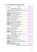
1.3 List of Maintenance-mode Functions.......................................................................... 7-2
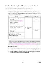
1.4 Detailed Description of Maintenance-mode Functions ............................................... 7-3
1.4.1 EEPROM parameter initialization (Function code 01, 91) ................................. 7-3
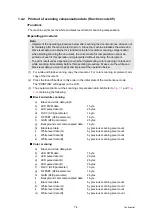
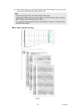
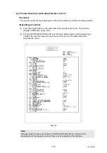
1.4.2 Printout of scanning compensation data (Function code 05)............................. 7-4
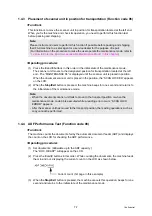
1.4.3 Placement of scanner unit in position for transportation (Function code 06)..... 7-7
1.4.4 ADF Performance Test (Function code 08) ....................................................... 7-7
1.4.5 Monochrome image quality test pattern (Function code 09).............................. 7-8
1.4.6 Worker switch (WSW) setting and printout (Function code 10, 11) ................... 7-9
1.4.7 Operational check of LCD (Function code 12) ................................................ 7-13
1.4.8 Operational check of control panel button (Function code 13) ........................ 7-14
1.4.9 Software version check (Function code 25)..................................................... 7-15
1.4.10 Operational check of sensors (Function code 32) ......................................... 7-16
1.4.11 PC print function (Function code 43) ............................................................. 7-20
1.4.12 Not-disclosed-to-users functions (Function code 45) .................................... 7-23
1.4.13 EEPROM customizing (User-accessible) (Function code 52) ....................... 7-27
1.4.14 Received data transfer function (Function code 53) (FAX model only) ......... 7-28
1.4.15 Fine adjustment of scan start/end positions (Function code 54) ................... 7-30
1.4.16 Acquisition of white level data (Function code 55)......................................... 7-31
1.4.17 Adjustment of color registration (Function code 66) ...................................... 7-32
1.4.18 Continuous print test (Function code 67)....................................................... 7-35
1.4.19 LED test pattern print (Function code 68)...................................................... 7-37
1.4.20 Frame pattern print (Function code 69) ......................................................... 7-39
1.4.21 Color test pattern (Function code 71) ............................................................ 7-41
1.4.22 Sensitivity adjustment of density sensor (Function code 72)......................... 7-43
1.4.23 Setting by country (Function code 74)........................................................... 7-44
1.4.24 Sensitivity adjustment of registration mark sensor and check of belt surface
Summary of Contents for DCP-9010CN
Page 11: ...Confidential CHAPTER 1 SPECIFICATIONS ...
Page 53: ...Confidential CHAPTER 2 THEORY OF OPERATION ...
Page 90: ...Confidential CHAPTER 3 ERROR INDICATION AND TROUBLESHOOTING ...
Page 201: ...Confidential CHAPTER 4 PERIODICAL MAINTENANCE ...
Page 224: ...Confidential CHAPTER 5 DISASSEMBLY AND ASSEMBLY ...
Page 440: ...Confidential CHAPTER 6 ADJUSTMENTS AND UPDATING OF SETTINGS REQUIRED AFTER PARTS REPLACEMENT ...
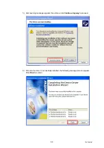
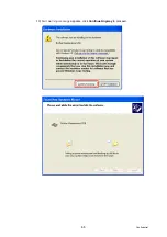
Page 446: ...6 5 Confidential 10 Alert warning message appears click Continue Anyway to proceed ...
Page 456: ...Confidential CHAPTER 7 SERVICE FUNCTIONS ...
Page 464: ...7 6 Confidential For color scanning Fig 7 2 ...
Page 487: ...7 29 Confidential Cover page sample Fig 7 13 End page sample Fig 7 14 ...
Page 492: ...7 34 Confidential Color registration adjustment chart Fig 7 16 ...
Page 496: ...7 38 Confidential LED test pattern M68_L Fig 7 18 ...
Page 498: ...7 40 Confidential Fig 7 19 ...
Page 500: ...7 42 Confidential Color test pattern Fig 7 20 MCYK Y C K M YCMK_ _A ...
Page 518: ...Confidential CHAPTER 8 CIRCUIT DIAGRAMS WIRING DIAGRAM ...
Page 521: ...Confidential 8 2 High voltage Power Supply PCB Circuit Diagram SYS HITEK SPH 8N35 2 3 ...
Page 522: ...Confidential 8 3 High voltage Power Supply PCB Circuit Diagram SYS HITEK SPH 8N35 3 3 ...
Page 523: ...Confidential 8 4 High voltage Power Supply PCB Circuit Diagram MURATA MPH3316 1 3 ...
Page 524: ...Confidential 8 5 High voltage Power Supply PCB Circuit Diagram MURATA MPH3316 2 3 ...
Page 525: ...Confidential 8 6 High voltage Power Supply PCB Circuit Diagram MURATA MPH3316 3 3 ...
Page 526: ...Confidential 8 7 Low voltage Power Supply PCB Circuit Diagram 100V ...
Page 527: ...Confidential 8 8 Low voltage Power Supply PCB Circuit Diagram 200V ...
Page 528: ...Confidential 8 9 NCU PCB Circuit Diagram USA Canada ...
Page 529: ...Confidential 8 10 NCU PCB Circuit Diagram Europe Asia Oceania China ...
Page 530: ...Confidential 8 11 NCU PCB Circuit Diagram South Africa Gulf ...
Page 531: ...Confidential 8 12 2 WIRING DIAGRAM Wiring Diagram 1 2 ...
Page 532: ...Confidential 8 13 Wiring Diagram 2 2 ...
Page 590: ...Confidential APPENDIX 3 SERIAL NUMBERING SYSTEM ...
Page 592: ...App 3 2 Confidential Serial number of the LED ASSY Print position Fig App 3 4 Serial number ...
Page 593: ...Confidential APPENDIX 4 SCREW CATALOGUE ...
Page 595: ...Confidential APPENDIX 5 REFERENCES ...
Page 597: ...Confidential APPENDIX 6 GLOSSARY ...


