6-1
Confidential
1.
IF YOU REPLACE THE MAIN PCB
■
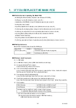
What to do when replacing the Main PCB
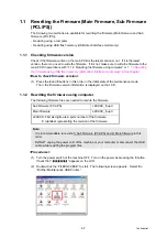
- Rewriting the firmware (Main firmware, sub firmware (PCL/PS))
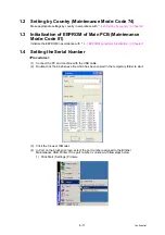
- Setting by country (Maintenance mode: code 74)
- Initialization of EEPROM of main PCB (Maintenance mode: code 01)
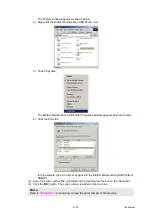
- Setting the serial number
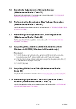
- Sensitivity adjustment of density sensor (Maintenance mode: code 72)
- Performing the developing bias voltage correction (Maintenance mode: code 83)
- Performing the adjustment of color registration (Maintenance mode: code 66)
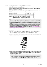
- Acquiring MAC address (Ethernet address) from wireless LAN PCB
(Wireless LAN model only)
- Acquiring white level data (Maintenance mode: code 55)
- Performing operational check of operation panel buttons (Maintenance mode: code 13)
■
Which parts to use
Main PCB: The table below shows the ROM type.
■
What you need to prepare
(1) A USB cable
(2) A USB flash memory drive (USB direct interface model only)
(3) Computer (Windows
®
XP or later)
Create a temporary folder on the C drive.
(4) The service setting tool (brusbn.zip)
Copy it into the temporary folder that has been created in the C drive. Extract the copied
file and execute “brusbsn.exe” file by double-clicking it.
(5) The download utility (FILEDG32.EXE)
Copy it into the temporary folder that has been created in the C drive.
(6) The Brother maintenance USB printer driver (MaintenanceDriver.zip)
Copy it into the temporary folder that has been created in the C drive. Extract the copied file.
(7) The firmware
* upd: Used to rewrite the firmware via a computer.
djf: Used to rewrite the firmware using a USB flash memory.
(USB direct interface model only)
Main PCB
(For a spare parts)
ROM 0
Main firmware
(Controller program, Network program)
ROM 1
Sub firmware (PCL/PS)
Main firmware
LZXXXX_$.djf or LZXXXX_$.upd*
Sub firmware
LZXXXX_$.djf or LZXXXX_$.upd
LZXXXX: First six digits are a parts number of the firmware.
$: Alphabet representing the revision of the firmware.
Summary of Contents for DCP-9010CN
Page 11: ...Confidential CHAPTER 1 SPECIFICATIONS ...
Page 53: ...Confidential CHAPTER 2 THEORY OF OPERATION ...
Page 90: ...Confidential CHAPTER 3 ERROR INDICATION AND TROUBLESHOOTING ...
Page 201: ...Confidential CHAPTER 4 PERIODICAL MAINTENANCE ...
Page 224: ...Confidential CHAPTER 5 DISASSEMBLY AND ASSEMBLY ...
Page 440: ...Confidential CHAPTER 6 ADJUSTMENTS AND UPDATING OF SETTINGS REQUIRED AFTER PARTS REPLACEMENT ...
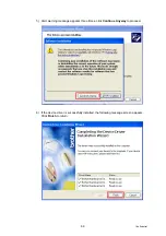
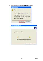
Page 446: ...6 5 Confidential 10 Alert warning message appears click Continue Anyway to proceed ...
Page 456: ...Confidential CHAPTER 7 SERVICE FUNCTIONS ...
Page 464: ...7 6 Confidential For color scanning Fig 7 2 ...
Page 487: ...7 29 Confidential Cover page sample Fig 7 13 End page sample Fig 7 14 ...
Page 492: ...7 34 Confidential Color registration adjustment chart Fig 7 16 ...
Page 496: ...7 38 Confidential LED test pattern M68_L Fig 7 18 ...
Page 498: ...7 40 Confidential Fig 7 19 ...
Page 500: ...7 42 Confidential Color test pattern Fig 7 20 MCYK Y C K M YCMK_ _A ...
Page 518: ...Confidential CHAPTER 8 CIRCUIT DIAGRAMS WIRING DIAGRAM ...
Page 521: ...Confidential 8 2 High voltage Power Supply PCB Circuit Diagram SYS HITEK SPH 8N35 2 3 ...
Page 522: ...Confidential 8 3 High voltage Power Supply PCB Circuit Diagram SYS HITEK SPH 8N35 3 3 ...
Page 523: ...Confidential 8 4 High voltage Power Supply PCB Circuit Diagram MURATA MPH3316 1 3 ...
Page 524: ...Confidential 8 5 High voltage Power Supply PCB Circuit Diagram MURATA MPH3316 2 3 ...
Page 525: ...Confidential 8 6 High voltage Power Supply PCB Circuit Diagram MURATA MPH3316 3 3 ...
Page 526: ...Confidential 8 7 Low voltage Power Supply PCB Circuit Diagram 100V ...
Page 527: ...Confidential 8 8 Low voltage Power Supply PCB Circuit Diagram 200V ...
Page 528: ...Confidential 8 9 NCU PCB Circuit Diagram USA Canada ...
Page 529: ...Confidential 8 10 NCU PCB Circuit Diagram Europe Asia Oceania China ...
Page 530: ...Confidential 8 11 NCU PCB Circuit Diagram South Africa Gulf ...
Page 531: ...Confidential 8 12 2 WIRING DIAGRAM Wiring Diagram 1 2 ...
Page 532: ...Confidential 8 13 Wiring Diagram 2 2 ...
Page 590: ...Confidential APPENDIX 3 SERIAL NUMBERING SYSTEM ...
Page 592: ...App 3 2 Confidential Serial number of the LED ASSY Print position Fig App 3 4 Serial number ...
Page 593: ...Confidential APPENDIX 4 SCREW CATALOGUE ...
Page 595: ...Confidential APPENDIX 5 REFERENCES ...
Page 597: ...Confidential APPENDIX 6 GLOSSARY ...

