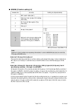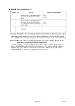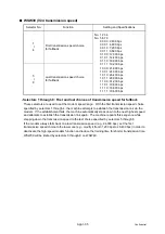
App.1-25
Confidential
■
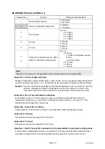
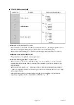
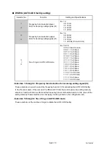
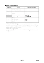
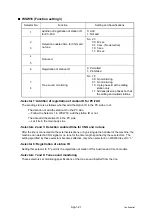
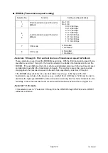
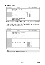
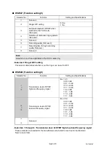
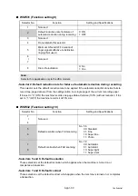
WSW23 (Communications setting)
- Selector 1: Starting point of training check (TCF)
At the training phase of receiving operation, the called station detects for 1.0 second a training
check (TCF) command, a series of zeros which is sent from the calling station for 1.5 seconds to
verify training and give the first indication of the acceptability of the line.
This selector sets the starting point from which the called station should start counting those zeros.
If this selector is set to “0,” the called station starts counting zeros 100 ms after the head of a series
of zeros is detected.
If it is set to “1,” the called station starts counting zeros upon detection of 10-ms successive zeros 50
ms after the head of a series of zeros is detected. In this case, if the detection of 10-ms successive
zeros is too late, the data counting period will become less than 1.0 second, making the called
station judge the line condition unacceptable.
- Selectors 2 and 3: Allowable training error rate
The called station checks a series of zeros gathered in training (as described in Selector 1)
according to the allowable training error rate set by these selectors. If the called station judges the
line condition to be accepted, it responds with CFR; if not, it responds with FTT.
- Selectors 4 and 5: Decoding error rate for transmission of RTN
The machine checks the actual decoding errors and then transmits an RTN according to the
decoding error rate (Number of lines containing an error per page ÷ Total number of lines per page)
set by these selectors.
- Selector 8: Limitation of attenuation level
Setting this selector to “0” limits the transmitting level of the modem to -10 dB. This setting has
priority over the settings selected by WSW02 (selectors 5 through 8) and WSW13 (selectors 5
through 8).
Selector No.
Function
Setting and Specifications
1
Starting point of training check (TCF)
0: 0 From the head of a series of zeros
1: From any arbitrary point
2
3
Allowable training error rate
No. 2 3
0 0: 0 %
0 1: 0.5 %
1 0: 1 %
1 1: 2 %
4
5
Decoding error rate for transmission
of RTN
No. 4 5
0 0: 16 %
0 1: 14 %
1 0: 10 %
1 1: 8 %
6
7
Not used.
8
Limitation of attenuation level
0: Yes
1: No
Note:
Selector 8 is not applicable to the French/Japan/China models.
Summary of Contents for DCP-9010CN
Page 11: ...Confidential CHAPTER 1 SPECIFICATIONS ...
Page 53: ...Confidential CHAPTER 2 THEORY OF OPERATION ...
Page 90: ...Confidential CHAPTER 3 ERROR INDICATION AND TROUBLESHOOTING ...
Page 201: ...Confidential CHAPTER 4 PERIODICAL MAINTENANCE ...
Page 224: ...Confidential CHAPTER 5 DISASSEMBLY AND ASSEMBLY ...
Page 440: ...Confidential CHAPTER 6 ADJUSTMENTS AND UPDATING OF SETTINGS REQUIRED AFTER PARTS REPLACEMENT ...
Page 446: ...6 5 Confidential 10 Alert warning message appears click Continue Anyway to proceed ...
Page 456: ...Confidential CHAPTER 7 SERVICE FUNCTIONS ...
Page 464: ...7 6 Confidential For color scanning Fig 7 2 ...
Page 487: ...7 29 Confidential Cover page sample Fig 7 13 End page sample Fig 7 14 ...
Page 492: ...7 34 Confidential Color registration adjustment chart Fig 7 16 ...
Page 496: ...7 38 Confidential LED test pattern M68_L Fig 7 18 ...
Page 498: ...7 40 Confidential Fig 7 19 ...
Page 500: ...7 42 Confidential Color test pattern Fig 7 20 MCYK Y C K M YCMK_ _A ...
Page 518: ...Confidential CHAPTER 8 CIRCUIT DIAGRAMS WIRING DIAGRAM ...
Page 521: ...Confidential 8 2 High voltage Power Supply PCB Circuit Diagram SYS HITEK SPH 8N35 2 3 ...
Page 522: ...Confidential 8 3 High voltage Power Supply PCB Circuit Diagram SYS HITEK SPH 8N35 3 3 ...
Page 523: ...Confidential 8 4 High voltage Power Supply PCB Circuit Diagram MURATA MPH3316 1 3 ...
Page 524: ...Confidential 8 5 High voltage Power Supply PCB Circuit Diagram MURATA MPH3316 2 3 ...
Page 525: ...Confidential 8 6 High voltage Power Supply PCB Circuit Diagram MURATA MPH3316 3 3 ...
Page 526: ...Confidential 8 7 Low voltage Power Supply PCB Circuit Diagram 100V ...
Page 527: ...Confidential 8 8 Low voltage Power Supply PCB Circuit Diagram 200V ...
Page 528: ...Confidential 8 9 NCU PCB Circuit Diagram USA Canada ...
Page 529: ...Confidential 8 10 NCU PCB Circuit Diagram Europe Asia Oceania China ...
Page 530: ...Confidential 8 11 NCU PCB Circuit Diagram South Africa Gulf ...
Page 531: ...Confidential 8 12 2 WIRING DIAGRAM Wiring Diagram 1 2 ...
Page 532: ...Confidential 8 13 Wiring Diagram 2 2 ...
Page 590: ...Confidential APPENDIX 3 SERIAL NUMBERING SYSTEM ...
Page 592: ...App 3 2 Confidential Serial number of the LED ASSY Print position Fig App 3 4 Serial number ...
Page 593: ...Confidential APPENDIX 4 SCREW CATALOGUE ...
Page 595: ...Confidential APPENDIX 5 REFERENCES ...
Page 597: ...Confidential APPENDIX 6 GLOSSARY ...


