2-35
Confidential
■
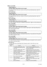
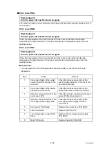
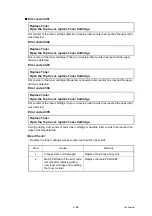
Error code 0501
The center thermistor of the fuser unit does not reach the specified temperature within the
specified time.
Error code 0502
The center thermistor of the fuser unit does not reach the specified temperature within the
specified time.
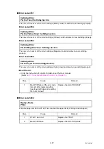
Error code 0503
The center thermistor of the fuser unit detected a temperature higher than the specified value.
Error code 0504
After the center thermistor of the fuser unit was normally heated, it detected a temperature
lower than the specified value.
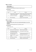
Error code 0505
The center thermistor of the fuser unit detected a temperature rise greater than the specified
value within a set period of time.
Error code 0506
The center thermistor of the fuser unit detected a temperature fall greater than the specified
value within a set period of time.
<User Check>
- Turn the power OFF and ON again after several seconds to check if the error code
disappears.
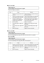
Print Unable 05
Turn the power off and then back on again.
Print Unable 05
Turn the power off and then back on again.
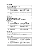
Print Unable 05
Turn the power off and then back on again.
Print Unable 05
Turn the power off and then back on again.
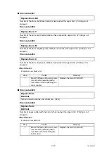
Print Unable 05
Turn the power off and then back on again.
Print Unable 05
Turn the power off and then back on again.
Step
Cause
Remedy
1
Connection failure of the center
or side thermistor harness of the
fuser unit
Check the harness connection of the
center or side thermistor of the fuser unit
and reconnect them.
2
Connection failure of the heater
harness of the fuser unit
Check the harness connection of the
heater of the fuser unit and reconnect it.
3
Harness connection failure of the
eject sensor PCB
Check the harness connection of the eject
sensor PCB and reconnect it.
4
Harness connection failure of the
low-voltage power supply PCB
Check the harness connection of the
low-voltage power supply PCB and
reconnect it.
5
Eject sensor PCB failure
Replace the eject sensor PCB ASSY.
6
Fuser unit failure
Replace the fuser unit.
7
Low-voltage power supply PCB
failure
Replace the low-voltage power supply
PCB ASSY.
8
Main PCB failure
Replace the main PCB ASSY.
Summary of Contents for DCP-9020CDN
Page 47: ...2 8 Confidential 2 2 2 Scanning part Fig 2 4 ...
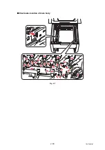
Page 89: ...2 50 Confidential Electrodes location of main body Fig 2 7 ...
Page 172: ...3 9 Confidential EM2 0 MOLYKOTE EM D110 2 0 mm dia ball EM2 0 Back cover ASSY Back cover ASSY ...
Page 345: ...5 7 Confidential Black and white scanning First side Front Fig 5 1 ...
Page 346: ...5 8 Confidential Black and white scanning Second side Back Fig 5 2 ...
Page 347: ...5 9 Confidential Color scanning First side Front Fig 5 3 ...
Page 348: ...5 10 Confidential Color scanning Second side Back Fig 5 4 ...
Page 384: ...5 46 Confidential LED test pattern M68_L Fig 5 17 ...
Page 429: ...App 3 8 Confidential When the following screen appears click Close to close the screen ...


