Confidential
3-55
8.15 Side Cover R ASSY
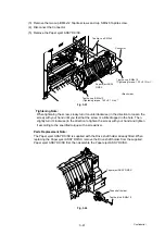
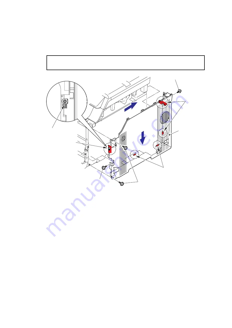
(1) Remove the two cup B M4x12 Taptite screws and two cup S M4x8 Taptite screws.
(2) Release the one Hook on the front side, two Hooks on the bottom and the two Hooks on
the back side, and then remove the Side cover R ASSY.
Note:
When removing the Side cover R ASSY, be careful not to damage section “A”.
Fig. 3-47
*1
Tightening Note:
When tightening the screw, slowly turn it counterclockwise (in the direction to loosen the
screw) with your hand until you feel that the screw is a little dropped in the hole. Then,
slightly turn it clockwise (in the direction to tighten the screw) with your hand and tighten
it according to the specified torque with a screwdriver.
Taptite, cup S M4x8
Hooks
Side cover R ASSY
“A”
Taptite, cup S M4x8
Taptite, cup B M4x12
(Tightening torque: 0.80
±
0.1 N m)
*1
Hooks
<Right side>
2a
2b
Hook
Summary of Contents for DCP-9040CN
Page 309: ...Confidential 4 5 8 Alert warning message of WHQL appears Click Continue Anyway to proceed ...
Page 325: ...Confidential 5 6 Color scanning Fig 5 2 ...
Page 342: ...Confidential 5 23 Cover page sample Fig 5 13 End page sample Fig 5 14 ...
Page 365: ...Confidential 6 2 Charge High voltage Power Supply PCB Circuit Diagram 2 4 ...
Page 366: ...Confidential 6 3 Charge High voltage Power Supply PCB Circuit Diagram 3 4 ...
Page 367: ...Confidential 6 4 Charge High voltage Power Supply PCB Circuit Diagram 4 4 ...
Page 368: ...Confidential 6 5 Transfer High voltage Power Supply PCB Circuit Diagram 1 2 ...
Page 369: ...Confidential 6 6 Transfer High voltage Power Supply PCB Circuit Diagram 2 2 ...
Page 370: ...Confidential 6 7 Low voltage Power Supply PCB Circuit Diagram 100V ...
Page 371: ...Confidential 6 8 Low voltage Power Supply PCB Circuit Diagram 200V ...
Page 373: ...Confidential 6 10 Filter PCB Circuit Diagram ...

