Confidential
3-137
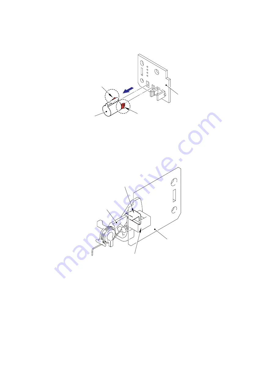
(6) Release the two Hooks of the LED holder to remove it from each of the four Toner sensor
PCB ASSYs (TE/NEW).
Fig. 3-195
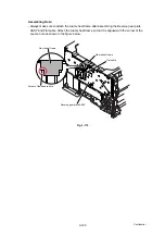
Assembling Note:
Assemble the Toner sensor PCB ASSY (TE/NEW) so that the Shutter of the New toner actuator
is put into the sensor section of the Toner sensor PCB ASSY (TE/NEW).
Fig. 3-196
Toner sensor PCB ASSY (TE/NEW)
LED holder
Hook
Hook
Toner sensor PCB ASSY (TE/ NEW)
Shutter
New toner actuator
Sensor section
Summary of Contents for DCP-9040CN
Page 309: ...Confidential 4 5 8 Alert warning message of WHQL appears Click Continue Anyway to proceed ...
Page 325: ...Confidential 5 6 Color scanning Fig 5 2 ...
Page 342: ...Confidential 5 23 Cover page sample Fig 5 13 End page sample Fig 5 14 ...
Page 365: ...Confidential 6 2 Charge High voltage Power Supply PCB Circuit Diagram 2 4 ...
Page 366: ...Confidential 6 3 Charge High voltage Power Supply PCB Circuit Diagram 3 4 ...
Page 367: ...Confidential 6 4 Charge High voltage Power Supply PCB Circuit Diagram 4 4 ...
Page 368: ...Confidential 6 5 Transfer High voltage Power Supply PCB Circuit Diagram 1 2 ...
Page 369: ...Confidential 6 6 Transfer High voltage Power Supply PCB Circuit Diagram 2 2 ...
Page 370: ...Confidential 6 7 Low voltage Power Supply PCB Circuit Diagram 100V ...
Page 371: ...Confidential 6 8 Low voltage Power Supply PCB Circuit Diagram 200V ...
Page 373: ...Confidential 6 10 Filter PCB Circuit Diagram ...

