Confidential
App. 1-23
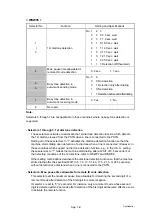
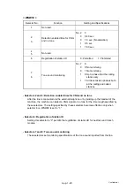
< WSW18 >
Selector No.
Function
Setting and Specifications
1 Not
used.
2
3
Detection enabled time for CNG
and no tone
No. 2 3
0 0: 40 sec.
0 1: 0 sec. (No detection)
1 0: 5 sec.
1 1: 80 sec.
4
5
Not used.
6
Registration of station ID
0: Permitted
1: Prohibited
7
8
Tone sound monitoring
No. 7 8
0 0: No monitoring
0 1: No monitoring
1 0: Up to phase B at the calling
station only
1 1: All transmission phases both
at the calling and called
stations
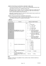
- Selectors 2 and 3: Detection enabled time for CNG and no tone
After the line is connected via the external telephone or by picking up the handset of the
machine, the machine can detect a CNG signal or no tone for the time length specified by
these selectors. The setting specified by these selectors becomes effective only when
selector 8 on WSW20 is set to “1.”
- Selector 6: Registration of station ID
Setting this selector to “0” permits the registration of station ID for Austrian and Czech
models.
- Selectors 7 and 8: Tone sound monitoring
These selectors set monitoring specifications of the tone sound inputted from the line.
Summary of Contents for DCP-9040CN
Page 309: ...Confidential 4 5 8 Alert warning message of WHQL appears Click Continue Anyway to proceed ...
Page 325: ...Confidential 5 6 Color scanning Fig 5 2 ...
Page 342: ...Confidential 5 23 Cover page sample Fig 5 13 End page sample Fig 5 14 ...
Page 365: ...Confidential 6 2 Charge High voltage Power Supply PCB Circuit Diagram 2 4 ...
Page 366: ...Confidential 6 3 Charge High voltage Power Supply PCB Circuit Diagram 3 4 ...
Page 367: ...Confidential 6 4 Charge High voltage Power Supply PCB Circuit Diagram 4 4 ...
Page 368: ...Confidential 6 5 Transfer High voltage Power Supply PCB Circuit Diagram 1 2 ...
Page 369: ...Confidential 6 6 Transfer High voltage Power Supply PCB Circuit Diagram 2 2 ...
Page 370: ...Confidential 6 7 Low voltage Power Supply PCB Circuit Diagram 100V ...
Page 371: ...Confidential 6 8 Low voltage Power Supply PCB Circuit Diagram 200V ...
Page 373: ...Confidential 6 10 Filter PCB Circuit Diagram ...

