Confidential
2-4
2.
PERIODICAL REPLACEMENT PARTS
2.1 Periodical Replacement Parts
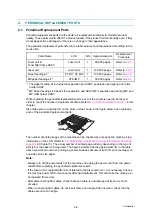
Periodical replacement parts are the parts to be replaced periodically to maintain product
quality. These parts would affect the product quality if they loose their functionality even if they
do not appear to be damaged or there is no change in their appearance.
The periodical replacement parts listed in the table below should be replaced according to the
service life.
Parts Name
LCD
Q’ty Approximate Life
Replacement
Procedure
Fuser unit &
Toner filter frame ASSY
Fuser Unit
1
80,000 pages
Refer to
Laser unit
Laser Unit
1
100,000 pages
Refer to
Paper feeding kit
*1
PF Kit1, PF Kit2
1
100,000 pages
Refer to
MP paper feeding kit
*2
PF KitMP
1
50,000 pages
Refer to
*1
: The paper feeding kit includes the separation pad ASSY, separation pad spring and roller
holder ASSY.
*2
: MP Paper feeding kit includes the separation pad ASSY MP, separation pad spring MP, and
MP roller holder ASSY.
When replacing the periodical replacement parts, each of the counters need to be reset in
order to count the number of replacement times. Refer to
“2.3 Parts Life Reset Function”
chapter.
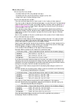
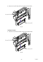
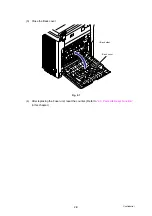
Also make sure to wipe the dirt on the drum unit as shown in the figure below when replacing
each of the periodical replacement parts.
The number of printed pages of the machine can be checked by accessing the machine’s log
information on the LCD. (Refer to
“1.4.23 Display of the Machine’s Log Information” (Function
in Chapter 5.) The actual number of printed page will vary depending on the type of
print job or the paper to being used. The figures indicated as the approximate life in the table
above are worked out when printing a general business document (with 5% print coverage) on
one side of A4-size paper.
Note:
- Always turn off the power switch of the machine and unplug the power cord from the power
outlet before replacing the periodical replacement parts.
- If the fuser unit is replaced after errors related to the fuser unit occur, it is necessary to leave
the machine power ON for ten minutes after part replacement. This will make the machine to
be released from errors.
- After disconnecting flat cables, check that each cable is not damaged at its end or short-
circuited.
- When connecting flat cables, do not insert them at an angle. After insertion, check that the
cables are not at an angle.
Summary of Contents for DCP-9040CN
Page 309: ...Confidential 4 5 8 Alert warning message of WHQL appears Click Continue Anyway to proceed ...
Page 325: ...Confidential 5 6 Color scanning Fig 5 2 ...
Page 342: ...Confidential 5 23 Cover page sample Fig 5 13 End page sample Fig 5 14 ...
Page 365: ...Confidential 6 2 Charge High voltage Power Supply PCB Circuit Diagram 2 4 ...
Page 366: ...Confidential 6 3 Charge High voltage Power Supply PCB Circuit Diagram 3 4 ...
Page 367: ...Confidential 6 4 Charge High voltage Power Supply PCB Circuit Diagram 4 4 ...
Page 368: ...Confidential 6 5 Transfer High voltage Power Supply PCB Circuit Diagram 1 2 ...
Page 369: ...Confidential 6 6 Transfer High voltage Power Supply PCB Circuit Diagram 2 2 ...
Page 370: ...Confidential 6 7 Low voltage Power Supply PCB Circuit Diagram 100V ...
Page 371: ...Confidential 6 8 Low voltage Power Supply PCB Circuit Diagram 200V ...
Page 373: ...Confidential 6 10 Filter PCB Circuit Diagram ...

