Confidential
2-2
Life
of
Drum Unit
<How to read the drum unit life>
- It initially indicates 100% and gradually decreases.
- It indicates 0% when the “Drum End Soon” appears on the LCD.
- It stays at 0% even if further printing is done.
<How to calculate the drum unit life>
The drum unit life is based on the “drum counter” or the “number of drum rotations”.
The drum counter is based on the total printed pages on each drum unit. This total printed
pages should be reset every time you replace the drum unit with a new one. (Refer to
in this chapter.) Basically this amount is equal to the assured
printable pages of the drum unit.
If the developing bias voltage correction or color registration adjustment is performed
frequently, however, only the number of drum rotations increases, and the “page counter
based on the number of drum rotation” exceeds the “drum counter” based on the total
printed page.
Refer to the calculation of the drum unit life based on the number of drum rotation below;
<How to calculate the page counter>
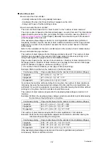
The number of drum rotations for the first page printed is about 27. The number of drum
rotations per one page for the second or later page printed (continuous printing) is 4.6.
Using these figures, the page counter is calculated as follows:
Page counter based on the number of drum rotations = (Number of drum rotations for the
first page p (Number of drum rotations per one page for the second or later page
printed x (Number of pages in continuous printing - 1))) / 27
(* The number of drum rotations per one page continuous printing.)
Example: Starts to print when the machine is in the Ready state.
Continuous printing
Page counter based on the number of drum rotations (Pages)
1 page/job
(27 + (4.6 x (1 - 1))) / 27 = 1
2 pages/job
(27 + (4.6 x (2 - 1))) / 27 = 1.17
18 pages/job
(27 + (4.6 x (18 - 1))) / 27 = 3.89
If you leave the machine without printing for a long time, the number of drum rotations is
increasing because the developing bias voltage correction and the color registration are
performed. If you print one page per one job every time after leaving the machine without
printing for a long time, the drum unit life is shorter than usual.
The number of drum rotations required for the developing bias voltage correction = 40
rotations.
Example: Performs the developing bias voltage correction and starts to print after leaving
the machine without printing for a long time.
Continuous printing
Page counter based on the number of drum rotations (Pages)
1 page/job
(40 + 27 + (4.6 x (1 - 1))) / 27 = 2.48
2 pages/job
(40 + 27 + (4.6 x (2 - 1))) / 27 = 2.65
18 pages/job
(40 + 27 + (4.6 x (18 - 1))) / 27 = 5.37
The number of drum rotations required for the color registration = 104 rotations
Example: Performs the color registration adjustment and starts to print after leaving the
machine without printing for a long time.
Continuous printing
Page counter based on the number of drum rotations (Pages)
1 page/job
(104 + 27 + (4.6 x (1 - 1))) / 27 = 4.85
2 pages/job
(104 + 27 + (4.6 x (2 - 1))) / 27 = 5.02
18 pages/job
(104 + 27 + (4.6 x (18 - 1))) / 27 = 7.75
If the developing bias voltage correction and the color registration are performed
continuously, the drum unit life is shorter.
Summary of Contents for DCP-9040CN
Page 309: ...Confidential 4 5 8 Alert warning message of WHQL appears Click Continue Anyway to proceed ...
Page 325: ...Confidential 5 6 Color scanning Fig 5 2 ...
Page 342: ...Confidential 5 23 Cover page sample Fig 5 13 End page sample Fig 5 14 ...
Page 365: ...Confidential 6 2 Charge High voltage Power Supply PCB Circuit Diagram 2 4 ...
Page 366: ...Confidential 6 3 Charge High voltage Power Supply PCB Circuit Diagram 3 4 ...
Page 367: ...Confidential 6 4 Charge High voltage Power Supply PCB Circuit Diagram 4 4 ...
Page 368: ...Confidential 6 5 Transfer High voltage Power Supply PCB Circuit Diagram 1 2 ...
Page 369: ...Confidential 6 6 Transfer High voltage Power Supply PCB Circuit Diagram 2 2 ...
Page 370: ...Confidential 6 7 Low voltage Power Supply PCB Circuit Diagram 100V ...
Page 371: ...Confidential 6 8 Low voltage Power Supply PCB Circuit Diagram 200V ...
Page 373: ...Confidential 6 10 Filter PCB Circuit Diagram ...


