3.INSTALLATION
RH-9800
9
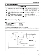
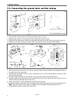
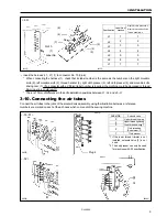
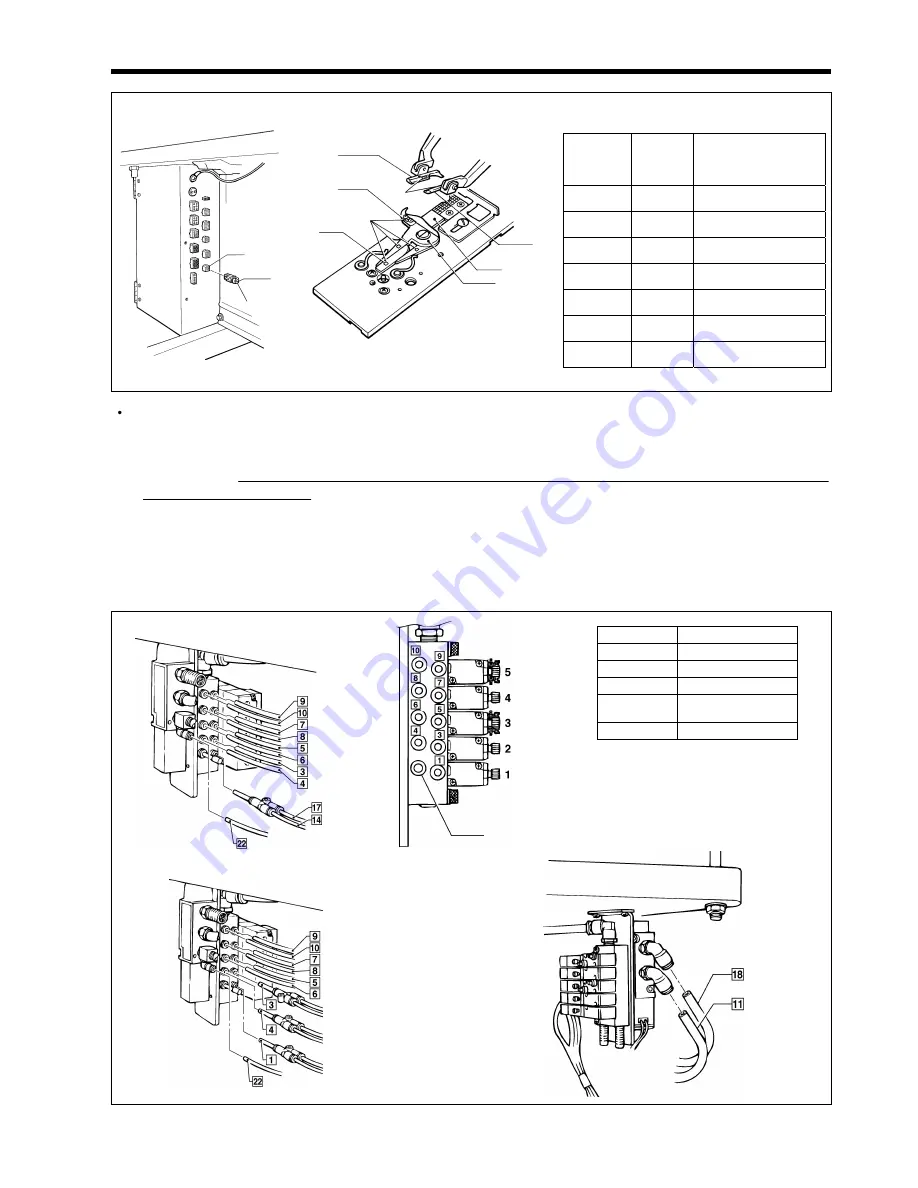
Insert the harness (L1 - L7) (1) to connector No. 10 (9-pin).
* When connecting the harness (1), check that its label number is the same as the numbers on the right movable
knife (2), left movable knife (3), thread handler (4), right cloth presser (5), left cloth presser (6) and movable knife
driving cam (7). (If a connector with a different label number is inserted, the machine could be damaged or thread
trimming errors could result.)
* There is 10 mm of difference in the knife installation positions between L1 - L4 and L5 - L7.
3-10. Connecting the air tubes
Connect the air tubes to the joints of the solenoid valve assembly, using the illustration below as a reference.
Numbers are marked on each of the air hoses which come out of the sewing machine.
Specification
Label No. of
harness
Right/left cloth presser No.
Right/left movable knife No.
Thread handler No.
L1
1
1
L2
2
2
L3
3
3
L4
4
4
L5
5
5
L6
6
6
L7
7
7
< -02 >
No.10
Label No.
(1)
1112Q
1113Q
No.
No.
(5)
(2)
(3)
(7)
(4)
(6)
Label No.
Solenoid valve
5
Upper thread trimming
4
Upper thread tightening
3
Lower thread trimming *1
2
Cloth spreading
(Sub presser *2)
1
Cloth presser
*1 If the lower thread trimmer is not
installed, solenoid valve [3] is not
used.
*2 The sub presser can only be used
for machines with -02 specification.
< -00,-01 >
< -02 >
0826Q
0827Q
Plug 4
0828Q
0829Q


