background image

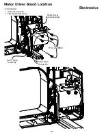
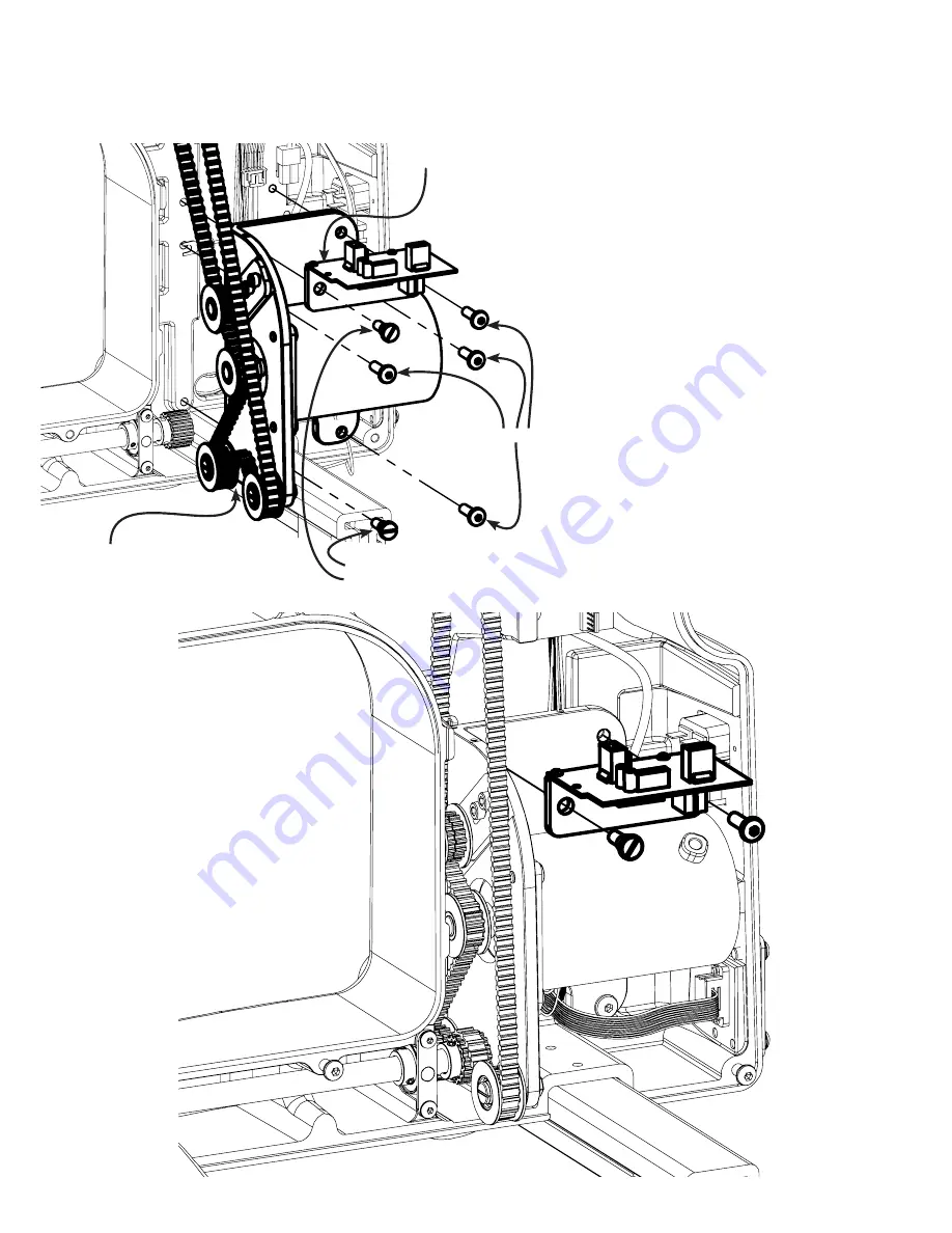
Motor Driver Board Location

21

Electronics

Motor Plate 

Assembly

Motor Driver 

Board Assembly

Pulley Base 

Thread Pin

M6 X 20 SBHCS

Tools Needed:

•  4mm Allen Wrench

•  Flat Head Screw Driver

Summary of Contents for Dream Quilter 15

Page 1: ...Service Manual Copyright Aug 01 2016 Jim M Bagley GraceWood Inc Reproduction Prohibited Version 1 ...

Page 2: ...Hook Holder 7 Timing the Sewing Machine 8 Handle Bars 9 Needle Plate 9 Thread Tensioner 10 Right Rear Pod 11 Front Housing 11 Needle Rod Holders 12 Upper Shaft 13 Main Board 16 Power Supply 17 Grounding Wire 17 Motor Driver Board Plugs 18 Optical Encoding Board 18 Grounding Wire 20 Idler Pulley Tension 20 ...

Page 3: ...et Screw Set Screw 2a If thread winds mostly on the top of the bobbin the Tension Discs Post will need to be lowered by twisting the Post Clockwise and retightening the hex nut 2b If thread winds mostly on the bottom of the bobbin the Tension Discs Post will need to be heightened by twisting the Post Counter Clockwise and retightening the hex nut Tools Needed 1 5mm Allen Wrench 9mm Crescent Wrench...

Page 4: ...Display Board Box Press here Press here 4 Assembly 4 Assembly Tools Needed Flat Head Screw Driver ...

Page 5: ...ight with a Flat Head Screw Driver here Needle Bar Thread Guide faces front of machine Height Spacer Flat Spot Tip of Needle Adjust Needle Bar Height 5 Assembly Tools Needed Needle Bar Height Spacer Flat Head Screw Driver ...

Page 6: ...ate align the hopping foot so that is centered 4 Place 8 sheets of paper under the foot and lower the hopping foot to the top of the surface You may need to use more or less sheets of paper if your project is particu larly thick or thin 5 Tighten the bolt using the 2mm allen wrench M3 Socket Head Thumb Screw Press Bar Needle Plate Hopping Foot 3mm Allen Wrench Green Handle M3 Socket Head Screw 6 A...

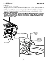
Page 7: ...f the hook assembly s positioning guide 3 Slide your hook holder away from the hook hssembly so there is about a 0 75mm gap it s hard to measure so just make it as big of a gap as possible with the hook holder still in the positioning guide between the hook holder and the hook assembly and tighten the M5 X 10 FHCS Tools Needed 3mm Allen Wrench Green Handle Hook Holder Hook Assembly 0 75mm Gap betw...

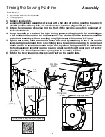
Page 8: ... and 0 075mm 5 Tighten set screw make sure needle doesn t hit hook by watching to see if the needle bends during rotation and there is no clicking noise Rotate machine using the handwheel a full rotation to ensure the needle doesn t hit anywhere during rotation If needle hits the hook assembly anywhere during rotation adjust needle height up or down off center from hook in 0 25mm increments as app...

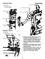
Page 9: ...l to ensure needle plate orientation so that all screw holes are visible and needle enters the middle of the needle plate without contacting the needle plate at any point 2 Attach your needle plate using 4 needle plate screws don t tighten the screws during this step 3 Rotate hand wheel until the needle is in the lowest position move needle plate till it is centered around needle and tighten all 4...

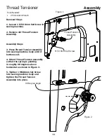
Page 10: ...Assembly so that the spring is pointing in roughly 90 degrees above horizontal as shown in Figure 2 5 Tighten 1 M5X8mm Set Screw into sewing machine body and tighten the Thread Tension Assembly into place 90 Degree Angle Removal Steps 1 Loosen 1 M5 X 8mm Set Screw in sewing machine 2 Remove old Thread Tension Assembly Thread Tension Assembly M5 X 8mm Set Screw Figure 1 Figure 2 ...

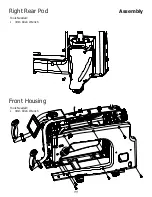
Page 11: ...Right Rear Pod Front Housing 11 Assembly Tools Needed 3mm Allen Wrench Tools Needed 4mm Allen Wrench ...

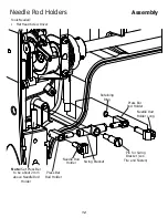
Page 12: ...r Rod Holder Retaining Ring Swing Bracket Pin for Swing Bracket Loc Tite and Fasten Needle Rod Holder Long Needle Rod Holder Note Set Press Bar to be about 2mm above Needle Rod Holder Tools Needed Flat Head Screw Driver Press Bar Rod Holder ...

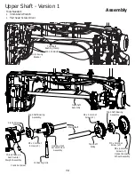
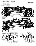
Page 13: ...for Swing Bracket Thread Take up And Counter Weight Assembly Crank Screw Crank Set Screw O Ring Connecting Link M3 x 3mm Set Screw x3 Top Shaft Bearing Assembly Hopping Foot Eccentric Cam Assembly Main Shaft Top Shaft Bearing Assembly M3 x 3mm Set Screw x3 M4 x 4mm Set Screw x3 Top Shaft Pulley M6 x 6mm Set Screw x2 Optical Encoding Wheel Assembly ...

Page 14: ...k Pin Thread Take up Assembly 6 35mm x 6mm Flat Set Screw Crank Screw Crank Set Screw Counter Weight M3 x 3mm Set Screw Top Shaft Bearing Assembly M4 x 4mm Set Screw M4 x 4mm Set Screw Hopping Foot Eccentric Cam Assembly Top Shaft Pulley M3 x 3mm Set Screw Top Shaft Bearing Assembly M6 x 6mm Set Screw M4 x 4mm Set Screw Handle Wheel M6 x 12mm Connector Bolt Optical Encoding Wheel Assembly Main Sha...

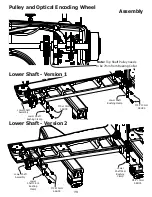
Page 15: ...Pulley needs to be 7mm from Bearing Collar Lower Shaft Version 2 M5 x 10mm SBHCS M5 x 10mm SBHCS Lower Shaft Rear Bushing Clamp Lower Shaft Front Bushing Clamp Lower Shaft Assembly M5 x 10mm SBHCS Lower Shaft Bushing Clamp Lower Shaft Assembly Lower Shaft Bushing Clamp M5 x 10mm SBHCS ...

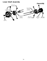
Page 16: ...haft Assembly 16 Assembly Hook Assembly Hook Assembly Set Screw x3 M4 x 4mm Set Screw x3 Lower Shaft Bearing Assembly Lower Shaft Pulley Lower Shaft Bearing Assembly M4 x 4mm Set Screw x3 M4 x 4mm Set Screw x3 ...

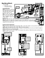
Page 17: ...e the screws loose Step 2 Slide the Bushing Block over the Adjustment Plate and thread the M5 x 16mm SBHCS Leave the screws loose Bushing Block Adjustment Tools Needed 3mm Allen Wrench 2 5mm Allen Wrench Step 3 Thread the M6 x 25mm Set Screws into the Bushing Block Step 4 Slide the needle bar through the top of the machine and through the bushing block then attach the needle bar thread guide and s...

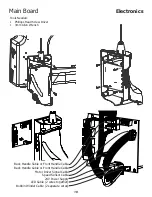
Page 18: ...e Cable Back Handle Cable or Front Handle Cable Motor Driver Signal Cable Speed Sensor Cable 24V Power Supply LED Cable 2 wires together Bobbin Winder Cable 2 separate wires 18 Electronics Tools Needed Phillops Head Screw Driver 3mm Allen Wrench ...

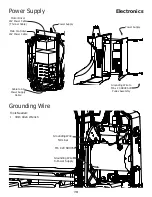
Page 19: ...ower Supply Grounding Wire to M6 x 20 SBHCS of Pulley Assembly Grounding Wire Terminal Tools Needed 4mm Allen Wrench Power Supply Power Supply Main Controller 24V Power Cable Motor Driver 24V Power Cable Thinner Cable Cable to AC Power Supply Cable 19 Electronics ...

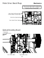
Page 20: ...Plugs Motor Driver 24V Power Cable Thinner Cable To Power Suply Motor Driver Signal Cable Motor Cable Thicker Cable Note Do not confuse the Motor Driver Cable and the Motor Power Cable If plugged in opposite it will burn out the board 20 Electronics Tools Needed 4mm Allen Wrench ...

Page 21: ...Motor Driver Board Location 21 Electronics Motor Plate Assembly Motor Driver Board Assembly Pulley Base Thread Pin M6 X 20 SBHCS Tools Needed 4mm Allen Wrench Flat Head Screw Driver ...

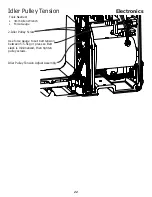
Page 22: ...ler Pulley Screw Idler Pulley Tension Adjust Assembly Use force gauge to set belt tension between 5 5 5kg or press so Belt slack is minimalized then tighten pulley screws 22 Electronics Tools Needed 4mm Allen Wrench Force Gauge ...

Reviews: