

V –
34
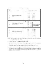
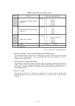
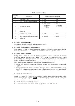
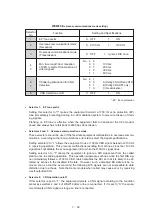
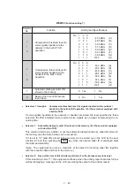
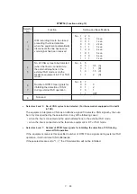
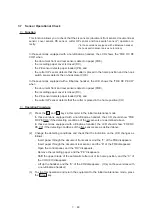
WSW23
(Communications setting)
Selector
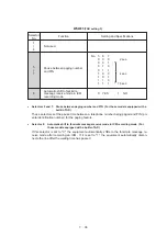
No.
Setting and Specifications
1
Starting point of training check
(TCF)
0: From the head of a series of zeros
1: From any arbitrary point
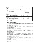
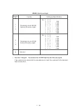
No. 2
3
0
0
:
0%
0
1
:
0.5%
1
0
:
1%
1
1
:
2%
Allowable training error rate
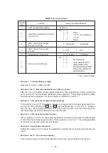
2
3
Function
Decoding error rate for
transmission of RTN
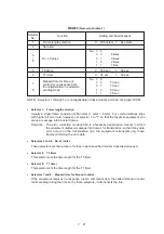
4
5
No. 4
5
0
0
:
16%
0
1
:
14%
1
0
:
10%
1
1
:
8%
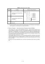
6
7
Not used.
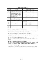
8
Limitation of attenuation level
0:
YES
1:
NO
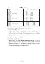
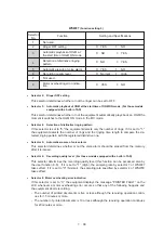
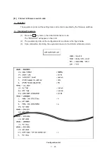
●
Selector 1:
Starting point of training check (TCF)
At the training phase of receiving operation, the called station detects for 1.0 second a train-
ing check (TCF) command, a series of zeros which is sent from the calling station for 1.5
seconds to verify training and give the first indication of the acceptability of the line.
This selector sets the starting point from which the called station should start counting those
zeros. If this selector is set to "0," the called station starts counting zeros 100 ms after the
head of a series of zeros is detected.
If it is set to "1," the called station starts counting zeros upon detection of 10-ms successive
zeros 50 ms after the head of a series of zeros is detected. In this case, if the detection of
10-ms successive zeros is too late, the data counting period will become less than 1.0 sec-
ond, making the called station judge the line condition unacceptable.
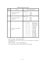
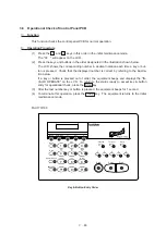
●
Selectors 2 and 3: Allowable training error rate
The called station checks a series of zeros gathered in training (as described in Selector 1)
according to the allowable training error rate set by these selectors. If the called station
judges the line condition to be accepted, it responds with CFR; if not, it responds with FTT.
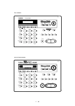
●
Selectors 4 and 5: Decoding error rate for transmission of RTN
The facsimile equipment checks the actual decoding errors and then transmits an RTN ac-
cording to the decoding error rate (Number of lines containing an error per page
÷
Total num-
ber of lines per page) set by these selectors.
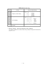
●
Selector 8:
Limitation of attenuation level
Setting this selector to "0" limits the transmitting level of the modem to 10 dB.
This setting has priority over the settings selected by WSW02 (selectors 5 through 8) and
WSW13 (selectors 5 through 8).
Summary of Contents for FAX-270MC
Page 4: ...CHAPTER I GENERAL DESCRIPTION ...
Page 11: ...CHAPTER II INSTALLATION ...
Page 12: ...CHAPTER III THEORY OF OPERATION ...
Page 49: ...CHAPTER IV DISASSEMBLY REASSEMBLY AND LUBRICATION ...
Page 86: ...IV 36 4 Cutter unit Cutter unit A A A A ...
Page 87: ...CHAPTER V MAINTENANCE MODE ...
Page 140: ...CHAPTER VI ERROR INDICATION AND TROUBLESHOOTING ...
Page 157: ...March 98 5X1S112 Printed in Japan ...
Page 173: ...D POWER SUPPLY 100 120 V U S A CANADA ...
Page 174: ...POWER SUPPLY 200 240 V EUROPE SOUTH AMERICA D ...
Page 175: ...POWER SUPPLY 200 240 V GULF ASIA CHINA D ...
Page 192: ...D POWER SUPPLY 100 120 V U S A CANADA ...
Page 193: ...POWER SUPPLY 200 240 V EUROPE SOUTH AMERICA D ...
Page 194: ...POWER SUPPLY 200 240 V GULF ASIA CHINA D ...
Page 195: ...FACSIMILE EQUIPMENT PARTS REFERENCE LIST MODEL FAX170 190 190 Plus 195 ...
Page 198: ......
Page 203: ......
Page 206: ...Remarks 8 8 8 8 8 8 9 9 8 8 8 8 8 8 0 1 0 1 Brother Technical Information FAX98250 4 ...
Page 208: ... 8 01 8 01 8 8 8 8 0 1 0 1 8 8 8 8 Brother Technical Information FAX99102 6 ...
Page 220: ......


