


V –
40
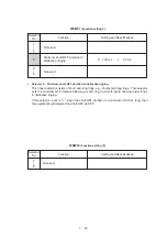
Function
Setting and Specifications
No. 1
2
3
0
0
0
:
-47.0 dBm
(A)
0
0
1
:
-48.5 dBm
(B)
0
1
0
:
-50.0 dBm
(C)
0
1
1
:
-51.5 dBm
(D)
1
0
0
:
-53.0 dBm
(E)
1
0
1
:
-54.5 dBm
(F)
1
1
0
:
-56.0 dBm
(G)
1
1
1
:
OFF
(H)
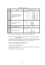
WSW29
(Function setting 7)
Selector
No.
1
|
3
4
|
6
No. 4
5
6
0
0
0
:
-44.0 dBm
(A)
0
0
1
:
-45.5 dBm
(B)
0
1
0
:
-47.0 dBm
(C)
0
1
1
:
-48.5 dBm
(D)
1
0
0
:
-50.0 dBm
(E)
1
0
1
:
-51.5 dBm
(F)
1
1
0
:
-53.0 dBm
(G)
1
1
1
:
OFF
(H)
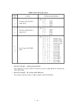
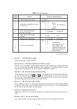
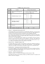
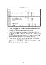
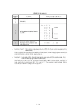
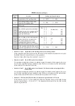
●
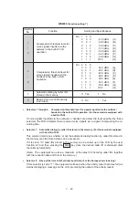
Selectors 1 through 6:
Compression threshold level for signals inputted via the network/
handset in the built-in TAD operation (For those models equipped with
a built-in TAD)
If voice signals inputted via the network or handset are below the level specified by these
selectors, the TAD interprets those received voice signals as no signal, compressing the re-
cording time.
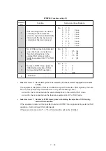
●
Selector 7:
Automatic dialing by caller IDs stored in the memory (For those models equipped
with a built-in TAD)
This selector determines whether or not the automatic dialing function by caller IDs stored in
the memory (see the Note below) can be accessed.
If it is set to "0," caller IDs stored in the memory can be called up on the LCD by the user
function 6-7 and then pressing the Start key when the desired caller ID is displayed dials
the caller automatically.
(Note: The equipment can store a maximum of the latest 30 incoming caller IDs together
with the reception date and time in the memory.)
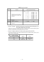
●
Selector 8:
Beep at the time of full activity report data (For the European versions only)
If this selector is set to "1," the equipment will beep when the activity report becomes full (as
well as displaying a message on the LCD, prompting the output of the activity report).
Compression threshold level for
voice signals inputted via the
network in the built-in TAD
operation
Compression threshold level for
voice signals inputted via the
handset in the built-in TAD
operation
0:
Yes
1:
No
7
Automatic dialing by caller IDs
stored in the memory
Beep at the time of full activity
report data
8
0:
No
1:
Yes
Summary of Contents for FAX-270MC
Page 4: ...CHAPTER I GENERAL DESCRIPTION ...
Page 11: ...CHAPTER II INSTALLATION ...
Page 12: ...CHAPTER III THEORY OF OPERATION ...
Page 49: ...CHAPTER IV DISASSEMBLY REASSEMBLY AND LUBRICATION ...
Page 86: ...IV 36 4 Cutter unit Cutter unit A A A A ...
Page 87: ...CHAPTER V MAINTENANCE MODE ...
Page 140: ...CHAPTER VI ERROR INDICATION AND TROUBLESHOOTING ...
Page 157: ...March 98 5X1S112 Printed in Japan ...
Page 173: ...D POWER SUPPLY 100 120 V U S A CANADA ...
Page 174: ...POWER SUPPLY 200 240 V EUROPE SOUTH AMERICA D ...
Page 175: ...POWER SUPPLY 200 240 V GULF ASIA CHINA D ...
Page 192: ...D POWER SUPPLY 100 120 V U S A CANADA ...
Page 193: ...POWER SUPPLY 200 240 V EUROPE SOUTH AMERICA D ...
Page 194: ...POWER SUPPLY 200 240 V GULF ASIA CHINA D ...
Page 195: ...FACSIMILE EQUIPMENT PARTS REFERENCE LIST MODEL FAX170 190 190 Plus 195 ...
Page 198: ......
Page 203: ......
Page 206: ...Remarks 8 8 8 8 8 8 9 9 8 8 8 8 8 8 0 1 0 1 Brother Technical Information FAX98250 4 ...
Page 208: ... 8 01 8 01 8 8 8 8 0 1 0 1 8 8 8 8 Brother Technical Information FAX99102 6 ...
Page 220: ......