III –
19
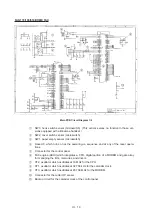
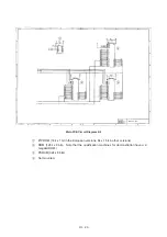
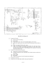
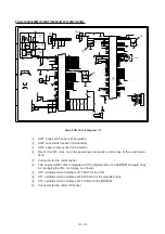
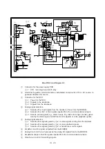
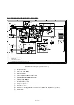
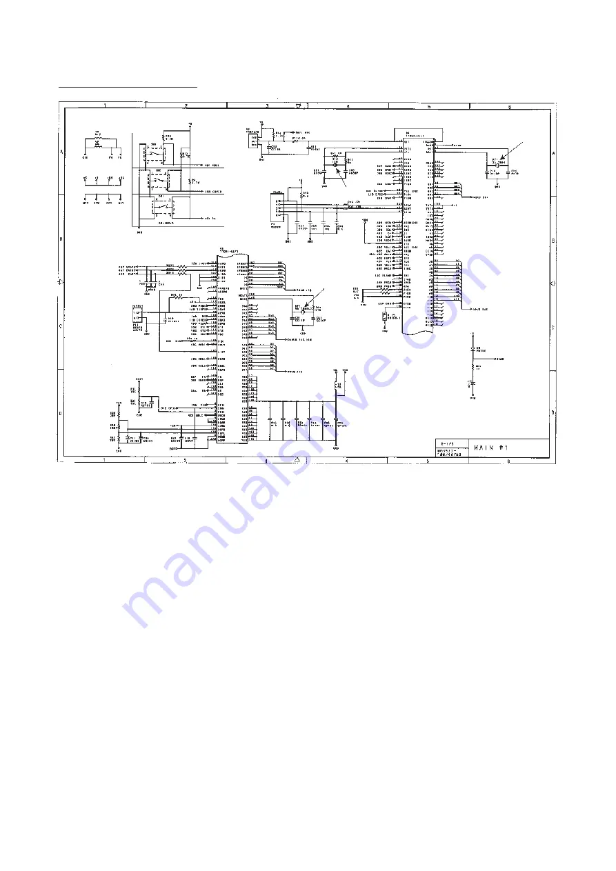
Main PCB Circuit Diagram 1/4
1
SW3, hook switch sensor (microswitch) (This sensor serves no function in those ver-
sions equipped with a Binatone handset.)
2
SW2, cover switch sensor (microswitch)
3
SW1, paper empty sensor (microswitch)
4
Reset IC which turns on at the powering-on sequence and at any of the reset opera-
tions.
5
Connector for the control panel
6
FAX engine (ASIC) which integrates a CPU, digital portion of a MODEM and gate array
for managing the I/Os, memories, and drivers.
7
XT2, oscillator which oscillates at 16 MHz for the CPU.
8
XT1, oscillator which oscillates at 32.768 kHz for the calendar clock.
9
XT3, oscillator which oscillates at 20.736 MHz for the MODEM.
:
Connector for the cutter HP sensor
a
Backup circuit for the calendar clock of the control panel
1
2
3
4
5
6
7
8
9
:
a
FAX-170/190/510/HOME FAX
Summary of Contents for FAX-270MC
Page 4: ...CHAPTER I GENERAL DESCRIPTION ...
Page 11: ...CHAPTER II INSTALLATION ...
Page 12: ...CHAPTER III THEORY OF OPERATION ...
Page 49: ...CHAPTER IV DISASSEMBLY REASSEMBLY AND LUBRICATION ...
Page 86: ...IV 36 4 Cutter unit Cutter unit A A A A ...
Page 87: ...CHAPTER V MAINTENANCE MODE ...
Page 140: ...CHAPTER VI ERROR INDICATION AND TROUBLESHOOTING ...
Page 157: ...March 98 5X1S112 Printed in Japan ...
Page 173: ...D POWER SUPPLY 100 120 V U S A CANADA ...
Page 174: ...POWER SUPPLY 200 240 V EUROPE SOUTH AMERICA D ...
Page 175: ...POWER SUPPLY 200 240 V GULF ASIA CHINA D ...
Page 192: ...D POWER SUPPLY 100 120 V U S A CANADA ...
Page 193: ...POWER SUPPLY 200 240 V EUROPE SOUTH AMERICA D ...
Page 194: ...POWER SUPPLY 200 240 V GULF ASIA CHINA D ...
Page 195: ...FACSIMILE EQUIPMENT PARTS REFERENCE LIST MODEL FAX170 190 190 Plus 195 ...
Page 198: ......
Page 203: ......
Page 206: ...Remarks 8 8 8 8 8 8 9 9 8 8 8 8 8 8 0 1 0 1 Brother Technical Information FAX98250 4 ...
Page 208: ... 8 01 8 01 8 8 8 8 0 1 0 1 8 8 8 8 Brother Technical Information FAX99102 6 ...
Page 220: ......