
IV –
6
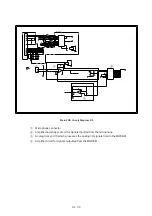
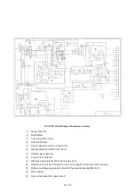
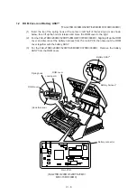
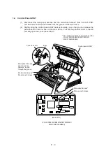
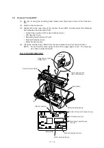
Main PCB
SW1
P13
P1
SW2
P2
P15
P16
P6
P12
P4
P3
P8
P7
SW3
P10
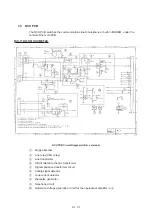
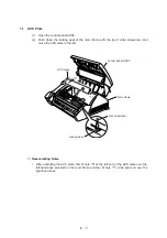
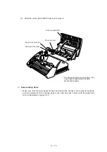
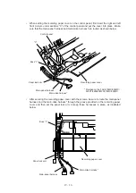
ROM cover
Locking arm
Spring hook
ROM cover
(Hook this area.)
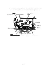
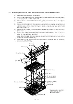
Battery connector
Battery harness*
Battery ASSY*
Main PCB
(FAX-270MC/290MC/520DT/520MC/
MFC370MC/390MC)
1.2
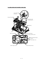
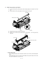
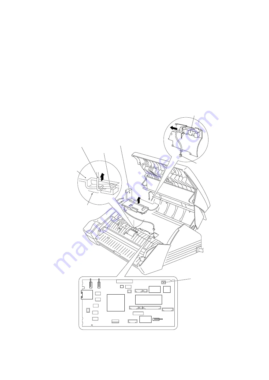
ROM Cover and Battery ASSY*
(*FAX-270MC/290MC/520DT/520MC/MFC370MC/390MC)
(1)
Insert the tip of the spring hook at the center or left half of the locking arm as shown
below, then lift up the hook to release and move the ROM cover to the right.
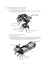
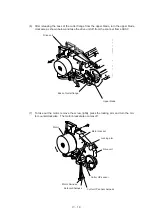
(2)
For the FAX-270MC/290MC/520DT/520MC/MFC370MC/390MC: Slightly lift up the ROM
cover and disconnect the battery harness from the main PCB, then take out the ROM
cover together with the battery ASSY.
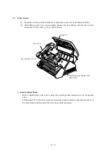
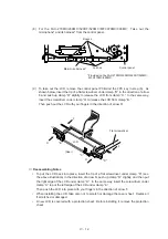
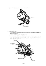
(3)
For the FAX-270MC/290MC/520DT/520MC/MFC370MC/390MC: Remove the battery
ASSY from the ROM cover.
Summary of Contents for FAX-270MC
Page 4: ...CHAPTER I GENERAL DESCRIPTION ...
Page 11: ...CHAPTER II INSTALLATION ...
Page 12: ...CHAPTER III THEORY OF OPERATION ...
Page 49: ...CHAPTER IV DISASSEMBLY REASSEMBLY AND LUBRICATION ...
Page 86: ...IV 36 4 Cutter unit Cutter unit A A A A ...
Page 87: ...CHAPTER V MAINTENANCE MODE ...
Page 140: ...CHAPTER VI ERROR INDICATION AND TROUBLESHOOTING ...
Page 157: ...March 98 5X1S112 Printed in Japan ...
Page 173: ...D POWER SUPPLY 100 120 V U S A CANADA ...
Page 174: ...POWER SUPPLY 200 240 V EUROPE SOUTH AMERICA D ...
Page 175: ...POWER SUPPLY 200 240 V GULF ASIA CHINA D ...
Page 192: ...D POWER SUPPLY 100 120 V U S A CANADA ...
Page 193: ...POWER SUPPLY 200 240 V EUROPE SOUTH AMERICA D ...
Page 194: ...POWER SUPPLY 200 240 V GULF ASIA CHINA D ...
Page 195: ...FACSIMILE EQUIPMENT PARTS REFERENCE LIST MODEL FAX170 190 190 Plus 195 ...
Page 198: ......
Page 203: ......
Page 206: ...Remarks 8 8 8 8 8 8 9 9 8 8 8 8 8 8 0 1 0 1 Brother Technical Information FAX98250 4 ...
Page 208: ... 8 01 8 01 8 8 8 8 0 1 0 1 8 8 8 8 Brother Technical Information FAX99102 6 ...
Page 220: ......


