IV –
18
1.8
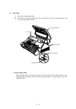
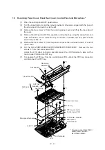
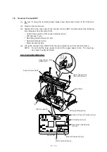
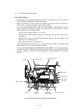
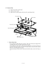
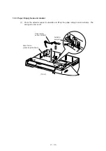
Drive Unit (Main Motor and Cutter HP Sensor)
(1)
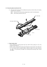
Turn the scanner frame ASSY upside down.
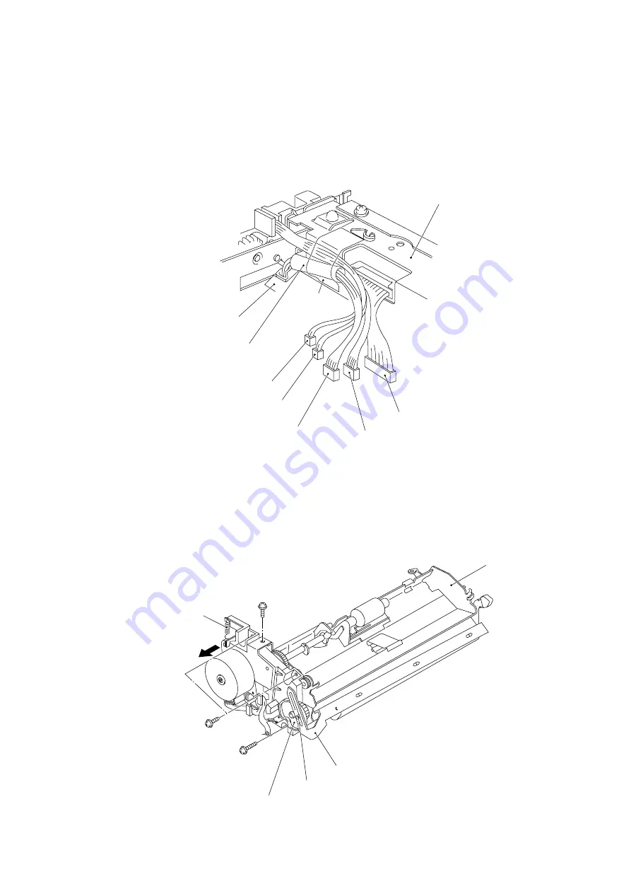
(2)
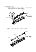
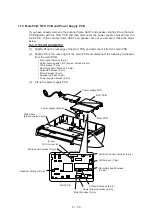
Remove the adhesive tape to release the CIS harness, motor harness, solenoid har-
ness, and cutter HP sensor harness.
Cutter HP sensor harness
Solenoid harness
Sheath of CIS harness
Lower paper chute
Recording head harness
Scanner frame ASSY
(placed upside down)
(Left)
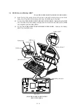
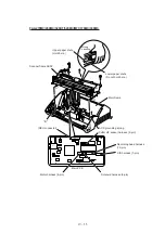
(3)
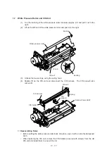
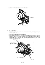
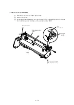
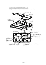
Place the scanner frame ASSY rightside up.
(4)
Remove the four screws.
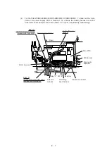
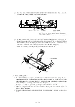
(5)
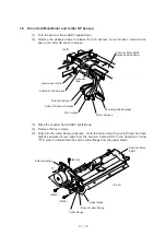
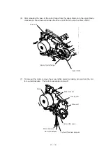
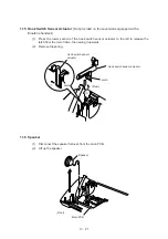
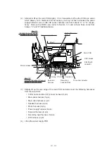
Fully turn the cutter flange clockwise. Hold the drive unit with your left hand and then
slightly separate its rear edge from the scanner frame ASSY in the direction of arrow
"X" in order to release the boss of the cutter flange from the upper blade.
CIS harness
Motor harness
Adhesive
tape
Scanner frame
ASSY
Solenoid spring
Upper blade
Boss of cutter flange
Cutter flange
(Front)
"X"
(M3x8)
(M3x6)
(M3x6)
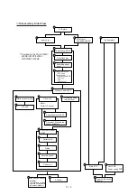
Summary of Contents for FAX-270MC
Page 4: ...CHAPTER I GENERAL DESCRIPTION ...
Page 11: ...CHAPTER II INSTALLATION ...
Page 12: ...CHAPTER III THEORY OF OPERATION ...
Page 49: ...CHAPTER IV DISASSEMBLY REASSEMBLY AND LUBRICATION ...
Page 86: ...IV 36 4 Cutter unit Cutter unit A A A A ...
Page 87: ...CHAPTER V MAINTENANCE MODE ...
Page 140: ...CHAPTER VI ERROR INDICATION AND TROUBLESHOOTING ...
Page 157: ...March 98 5X1S112 Printed in Japan ...
Page 173: ...D POWER SUPPLY 100 120 V U S A CANADA ...
Page 174: ...POWER SUPPLY 200 240 V EUROPE SOUTH AMERICA D ...
Page 175: ...POWER SUPPLY 200 240 V GULF ASIA CHINA D ...
Page 192: ...D POWER SUPPLY 100 120 V U S A CANADA ...
Page 193: ...POWER SUPPLY 200 240 V EUROPE SOUTH AMERICA D ...
Page 194: ...POWER SUPPLY 200 240 V GULF ASIA CHINA D ...
Page 195: ...FACSIMILE EQUIPMENT PARTS REFERENCE LIST MODEL FAX170 190 190 Plus 195 ...
Page 198: ......
Page 203: ......
Page 206: ...Remarks 8 8 8 8 8 8 9 9 8 8 8 8 8 8 0 1 0 1 Brother Technical Information FAX98250 4 ...
Page 208: ... 8 01 8 01 8 8 8 8 0 1 0 1 8 8 8 8 Brother Technical Information FAX99102 6 ...
Page 220: ......


