
V
- 9
3.5 Firmware Switch Setting and Printout
[ A ] Firmware switch setting
n
n
Function
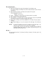
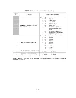
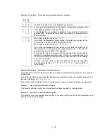
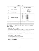
The facsimile equipment incorporates the following firmware switch functions (WSW01 through
WSW36) which may be activated with the procedures using the control panel keys and buttons.
The firmware switches have been set at the factory in conformity to the communications standards
and codes of each country. Do not disturb them unless necessary. Some firmware switches may
not be applicable in some versions. The firmware switch data list indicates "Not used." for those
inapplicable switches.
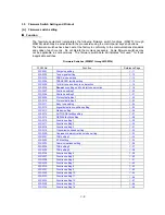
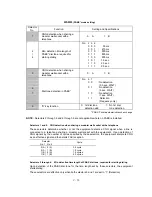
Firmware Switches (WSW01 through WSW36)
WSW No. Function Reference Page
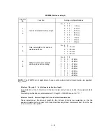
WSW01 Dial pulse setting
V
-11
WSW02 Tone signal setting
V
-12
WSW03 PABX mode setting
V
-13
WSW04 TRANSFER facility setting
V
-15
WSW05 1st dial tone and busy tone detection
V
-16
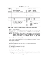
WSW06
Pause
key setting and 2nd dial tone detection
V
-18
WSW07 Dial tone setting 1
V
-20
WSW08 Dial tone setting 2
V
-21
WSW09 Protocol definition 1
V
-22
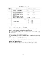
WSW10 Protocol definition 2
V
-23
WSW11 Busy tone setting
V
-24
WSW12 Signal detection condition setting
V
-25
WSW13 Modem setting
V
-26
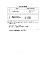
WSW14 AUTO ANS facility setting
V
-27
WSW15 REDIAL facility setting
V
-28
WSW16 Function setting 1
V
-29
WSW17 Function setting 2
V
-30
WSW18 Function setting 3
V
-31
WSW19 Transmission speed setting
V
-32
WSW20 Overseas communications mode setting
V
-33
WSW21 TAD setting 1
V
-34
WSW22 ECM setting
V
-35
WSW23 Communications setting
V
-36
WSW24 TAD setting 2
V
-37
WSW25 TAD setting 3
V
-38
WSW26 Function setting 4
V
-39
WSW27 Function setting 5
V
-40
WSW28 Function setting 6
V
-41
WSW29 Function setting 7
V
-42
WSW30 Function setting 8
V
-43
WSW31 Function setting 9
V
-44
WSW32 Function setting 10
V
-45
WSW33 Function setting 11
V
-46
WSW34 Function setting 12
V
-47
WSW35 Function setting 13
V
-48
WSW36 Function setting 14
V
-48
Summary of Contents for FAX 750
Page 4: ...CHAPTER I GENERAL DESCRIPTION ...
Page 11: ...CHAPTER II INSTALLATION ...
Page 12: ...CHAPTER III THEORY OF OPERATION ...
Page 14: ...III 1 1 OVERVIEW Not provided on the FAX 910 ...
Page 24: ...III 11 Active Gears on the Inner Side of the Drive Unit ...
Page 26: ...III 13 Active Gears on the Inner Side of the Drive Unit ...
Page 30: ...III 17 Location of Sensors and Actuators 1 ...
Page 31: ...III 18 Not provided on the FAX 910 Location of Sensors and Actuators 2 ...
Page 34: ...III 21 FAX750 FAX770 FAX 910 FAX 920 FAX 921 MFC 925 FAX870MC FAX 930 FAX 931 MFC970MC ...
Page 39: ...CHAPTER IV DISASSEMBLY REASSEMBLY LUBRICATION AND ADJUSTMENT ...
Page 44: ...IV 4 n n Disassembly Order Flow ...
Page 48: ...IV 8 4 Disconnect the panel main harness ...
Page 52: ...IV 12 ...
Page 70: ...IV 30 Remove the two screws and lift up the paper feed chute ...
Page 72: ...IV 32 ...
Page 78: ...IV 38 ...
Page 86: ...IV 46 1 17 Harness Routing ...
Page 88: ...IV 48 ...
Page 89: ...IV 49 2 LF roller ASSY 3 Platen frame ASSY ...
Page 90: ...IV 50 ...
Page 91: ...IV 51 4 Separation roller and main frame ...
Page 92: ...CHAPTER V MAINTENANCE MODE ...
Page 99: ...V 6 Scanning Compensation Data List ...
Page 150: ...CHAPTER VI ERROR INDICATION AND TROUBLESHOOTING ...
Page 168: ...July 98 5X4401 Printed in Japan ...
Page 177: ......
Page 178: ......
Page 182: ......
Page 184: ......
Page 197: ......
Page 198: ......
Page 202: ......
Page 216: ......
Page 218: ......