
V
- 19
l
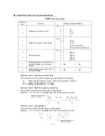
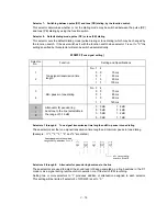
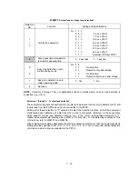
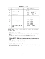
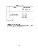
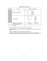
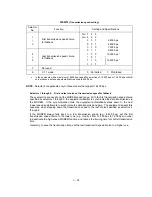
Selectors 1 through 3:
Pause key setting and 2nd dial tone detection
Selectors
1
2
3
0
0
0
No WAIT is inserted even if the
Pause
key is pressed.
0
0
1
0
1
0
0
1
1
1
0
0
If you press the
Pause
key during dialing, the facsimile equipment will
insert WAIT as defined in the above table.
If the
Pause
key is pressed repeatedly, the equipment inserts the
specified WAIT multiplied by the number of depressions. It applies also in
hook-up dialing.
1
0
1
1
1
0
1
1
1
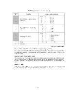
When these selectors are set to "1, 0, 1":
If you press the
Pause
key during dialing, the equipment will wait for the
2nd dial tone to be sent via the communications line.
When these selectors are set to "1, 1, 0" or "1, 1, 1":
If you press the
Pause
key during dialing, the equipment will first wait for
the 2nd dial tone to be sent via the communications line. After that, the
equipment will insert a WAIT of 3.5 seconds.
If no 2nd dial tone is received within the specified time length (set by
WSW08), the equipment will disconnect the line if in automatic dialing or it
will start transmitting the dial signal if given after depression of the
Pause
key in hook-up dialing.
(In those countries where no dial tone detection function is supported,
setting these selectors to "1, 1, 0," "1, 0, 1," or "1, 1, 1" inserts a WAIT of
3.5 seconds.)
l
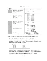
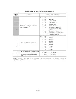
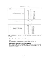
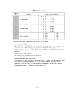
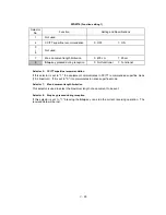
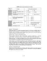
Selectors 4 through 6:
Detection of international tone
Upon detection of the 2nd dial tone for the time length specified by these selectors, the equipment
starts dialing.
This setting is effective only when the 2nd dial tone detection function is activated by selectors 1
through 3 (Setting 1 0 1, 1 1 0, or 1 1 1).
This function does not apply in those countries where no dial tone detection function is supported.
l
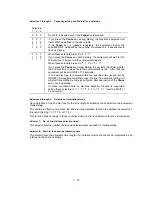
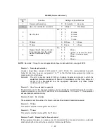
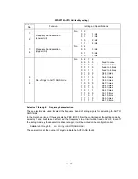
Selector 7:
No. of 2nd dial tone detection times
This selector sets the number of dial tone detection times required for starting dialing.
l
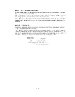
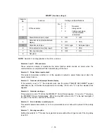
Selector 8:
2nd dial tone interrupt detecting time
This selector sets the allowable time length of an interrupt which should not be interpreted as an
interrupt in the 2nd tone dialing.
Summary of Contents for FAX 750
Page 4: ...CHAPTER I GENERAL DESCRIPTION ...
Page 11: ...CHAPTER II INSTALLATION ...
Page 12: ...CHAPTER III THEORY OF OPERATION ...
Page 14: ...III 1 1 OVERVIEW Not provided on the FAX 910 ...
Page 24: ...III 11 Active Gears on the Inner Side of the Drive Unit ...
Page 26: ...III 13 Active Gears on the Inner Side of the Drive Unit ...
Page 30: ...III 17 Location of Sensors and Actuators 1 ...
Page 31: ...III 18 Not provided on the FAX 910 Location of Sensors and Actuators 2 ...
Page 34: ...III 21 FAX750 FAX770 FAX 910 FAX 920 FAX 921 MFC 925 FAX870MC FAX 930 FAX 931 MFC970MC ...
Page 39: ...CHAPTER IV DISASSEMBLY REASSEMBLY LUBRICATION AND ADJUSTMENT ...
Page 44: ...IV 4 n n Disassembly Order Flow ...
Page 48: ...IV 8 4 Disconnect the panel main harness ...
Page 52: ...IV 12 ...
Page 70: ...IV 30 Remove the two screws and lift up the paper feed chute ...
Page 72: ...IV 32 ...
Page 78: ...IV 38 ...
Page 86: ...IV 46 1 17 Harness Routing ...
Page 88: ...IV 48 ...
Page 89: ...IV 49 2 LF roller ASSY 3 Platen frame ASSY ...
Page 90: ...IV 50 ...
Page 91: ...IV 51 4 Separation roller and main frame ...
Page 92: ...CHAPTER V MAINTENANCE MODE ...
Page 99: ...V 6 Scanning Compensation Data List ...
Page 150: ...CHAPTER VI ERROR INDICATION AND TROUBLESHOOTING ...
Page 168: ...July 98 5X4401 Printed in Japan ...
Page 177: ......
Page 178: ......
Page 182: ......
Page 184: ......
Page 197: ......
Page 198: ......
Page 202: ......
Page 216: ......
Page 218: ......