
V
- 26
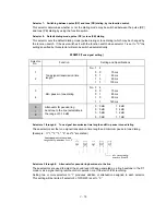
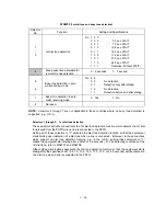
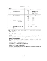
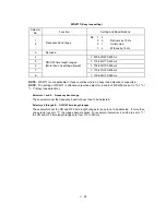
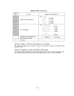
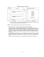
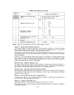
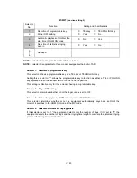
WSW13
(Modem setting)
Selector
No.
Function
Setting and Specifications
1
2
Cable equalizer
No. 1
2
0
0
:
0 km
0
1
:
1.8 km
1
0
:
3.6 km
1
1
:
5.6 km
3
4
Reception level
No. 3
4
0
0
:
-43 dBm
0
1
:
-47 dBm
1
0
:
-49 dBm
1
1
:
-51 dBm
5
|
8
Modem attenuator
0:
0 dB
1:
8 dB
0:
0 dB
1:
4 dB
0:
0 dB
1:
2 dB
0:
0 dB
1:
1 dB
The modem should be adjusted according to the user's line conditions.
l
Selectors 1 and 2: Cable equalizer
These selectors are used to improve the pass-band characteristics of analogue signals on a line.
(Attenuation in the high-band frequency is greater than in the low-band frequency.)
Set these selectors according to the distance from the telephone switchboard to the facsimile
equipment.
l
Selectors 3 and 4: Reception level
These selectors set the optimum receive signal level.
l
Selectors 5 through 8:
Modem attenuator
These selectors are used to adjust the transmitting level of the modem when the reception level at
the remote station is improper due to line loss. This function applies for G3 protocol signals.
Setting two or more selectors to "1" produces addition of attenuation assigned to each selector.
This setting will be limited if selector 8 of WSW23 is set to "0."
Summary of Contents for FAX 750
Page 4: ...CHAPTER I GENERAL DESCRIPTION ...
Page 11: ...CHAPTER II INSTALLATION ...
Page 12: ...CHAPTER III THEORY OF OPERATION ...
Page 14: ...III 1 1 OVERVIEW Not provided on the FAX 910 ...
Page 24: ...III 11 Active Gears on the Inner Side of the Drive Unit ...
Page 26: ...III 13 Active Gears on the Inner Side of the Drive Unit ...
Page 30: ...III 17 Location of Sensors and Actuators 1 ...
Page 31: ...III 18 Not provided on the FAX 910 Location of Sensors and Actuators 2 ...
Page 34: ...III 21 FAX750 FAX770 FAX 910 FAX 920 FAX 921 MFC 925 FAX870MC FAX 930 FAX 931 MFC970MC ...
Page 39: ...CHAPTER IV DISASSEMBLY REASSEMBLY LUBRICATION AND ADJUSTMENT ...
Page 44: ...IV 4 n n Disassembly Order Flow ...
Page 48: ...IV 8 4 Disconnect the panel main harness ...
Page 52: ...IV 12 ...
Page 70: ...IV 30 Remove the two screws and lift up the paper feed chute ...
Page 72: ...IV 32 ...
Page 78: ...IV 38 ...
Page 86: ...IV 46 1 17 Harness Routing ...
Page 88: ...IV 48 ...
Page 89: ...IV 49 2 LF roller ASSY 3 Platen frame ASSY ...
Page 90: ...IV 50 ...
Page 91: ...IV 51 4 Separation roller and main frame ...
Page 92: ...CHAPTER V MAINTENANCE MODE ...
Page 99: ...V 6 Scanning Compensation Data List ...
Page 150: ...CHAPTER VI ERROR INDICATION AND TROUBLESHOOTING ...
Page 168: ...July 98 5X4401 Printed in Japan ...
Page 177: ......
Page 178: ......
Page 182: ......
Page 184: ......
Page 197: ......
Page 198: ......
Page 202: ......
Page 216: ......
Page 218: ......