
V
- 37
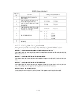
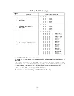
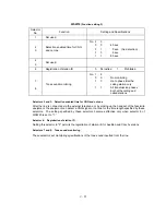
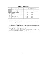
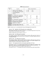
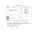
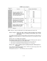
WSW24
(TAD setting 2)
Selector
No.
Function
Setting and Specifications
1
2
Maximum OGM recording time
No.
1
2
0
0
:
15 sec.
0
1
:
20 sec.
1
0
:
30 sec.
1
1
:
50 sec.
3
4
Time length from CML ON to
start of pseudo ring backtone
transmission
No.
3
4
0
0
:
4 sec.
0
1
:
3 sec.
1
0
:
2 sec.
1
1
:
1 sec.
5
|
8
Attenuator for playback of ICM/
OGM to the line
(Selectable from the range of 0-
15 dB)
0:
0 dB
1:
8 dB
0:
0 dB
1:
4 dB
0:
0 dB
1:
2 dB
0:
0 dB
1:
1 dB
NOTE:
Selectors 1 and 2 are applicable to those models equipped with a built-in TAD.
l
Selectors 1 and 2: Maximum OGM recording time
These selectors set the allowable maximum recording time for an OGM.
l
Selectors 3 and 4: Time length from CML ON to start of pseudo ring backtone transmission
These selectors set the length of time from CML-ON up to the start of pseudo ring backtone
transmission.
In those versions which have an OGM facility, the settings made by these selectors also apply to
the length of time from CML-ON up to the start of OGM transmission.
l
Selectors 5 through 8:
Attenuator for playback of ICM/OGM to the line
Setting two or more selectors to "1" produces addition of attenuation assigned to each selector.
This setting will not be limited by selector 8 of WSW23.
Summary of Contents for FAX 750
Page 4: ...CHAPTER I GENERAL DESCRIPTION ...
Page 11: ...CHAPTER II INSTALLATION ...
Page 12: ...CHAPTER III THEORY OF OPERATION ...
Page 14: ...III 1 1 OVERVIEW Not provided on the FAX 910 ...
Page 24: ...III 11 Active Gears on the Inner Side of the Drive Unit ...
Page 26: ...III 13 Active Gears on the Inner Side of the Drive Unit ...
Page 30: ...III 17 Location of Sensors and Actuators 1 ...
Page 31: ...III 18 Not provided on the FAX 910 Location of Sensors and Actuators 2 ...
Page 34: ...III 21 FAX750 FAX770 FAX 910 FAX 920 FAX 921 MFC 925 FAX870MC FAX 930 FAX 931 MFC970MC ...
Page 39: ...CHAPTER IV DISASSEMBLY REASSEMBLY LUBRICATION AND ADJUSTMENT ...
Page 44: ...IV 4 n n Disassembly Order Flow ...
Page 48: ...IV 8 4 Disconnect the panel main harness ...
Page 52: ...IV 12 ...
Page 70: ...IV 30 Remove the two screws and lift up the paper feed chute ...
Page 72: ...IV 32 ...
Page 78: ...IV 38 ...
Page 86: ...IV 46 1 17 Harness Routing ...
Page 88: ...IV 48 ...
Page 89: ...IV 49 2 LF roller ASSY 3 Platen frame ASSY ...
Page 90: ...IV 50 ...
Page 91: ...IV 51 4 Separation roller and main frame ...
Page 92: ...CHAPTER V MAINTENANCE MODE ...
Page 99: ...V 6 Scanning Compensation Data List ...
Page 150: ...CHAPTER VI ERROR INDICATION AND TROUBLESHOOTING ...
Page 168: ...July 98 5X4401 Printed in Japan ...
Page 177: ......
Page 178: ......
Page 182: ......
Page 184: ......
Page 197: ......
Page 198: ......
Page 202: ......
Page 216: ......
Page 218: ......


