


V
- 47
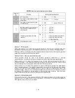
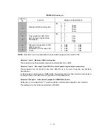
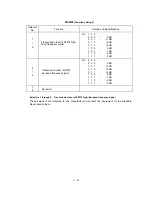
WSW34
(Function setting 12
)
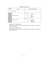
Selector
No.
Function
Setting and Specifications
1
|
3
Erasing time length of ICM tone
recorded preceding the tone
detection starting point in the case
of automatic line disconnection due
to no voice signal received
No. 1
2
3
0
0
0
:
0 sec.
0
0
1
:
1 sec.
0
1
0
:
2 sec.
0
1
1
:
3 sec.
1
0
0
:
4 sec.
1
0
1
:
5 sec.
1
1
0
:
6 sec.
1
1
1
:
7 sec.
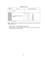
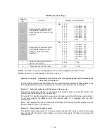
4
5
No. of CNG cycles to be detected
(when the line is connected via the
external telephone in the external
TAD mode or via the facsimile
equipment in F/T or TAD mode)
No. 4
5
0
0
:
0.5
(A)
0
1
:
1
(B)
1
0
:
1.5
(C)
1
1
:
2
(D)
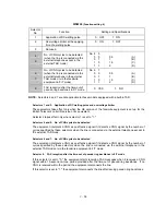
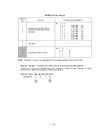
6
7
Number of DTMF tone signals for
inhibiting the detection of CNG
during external TAD operation
No. 6
7
0
0
:
3
0
1
:
2
1
0
:
1
1
1
:
OFF
8
Not used.
NOTE:
Selectors 1 through 5 are applicable to those models equipped with a built-in TAD.
l
Selectors 1 through 3:
Erasing time length of ICM tone recorded preceding the tone detection
starting point in the case of automatic line disconnection due to no voice
signal received
If the equipment has disconnected the line after detection of disconnection tone in ICM recording, it
erases tone recorded preceding the tone detection starting point for the time length set by these
selectors.
l
Selectors 4 and 5: No. of CNG cycles to be detected
The equipment interprets a CNG as an effective signal if it detects a CNG signal by the number of
cycles specified by these selectors in any of the following cases:
•
when the line is connected via the external telephone in the external TAD mode.
•
when the line is connected via the facsimile equipment in F/T or TAD mode.
l
Selectors 6 and 7: Number of DTMF tone signals for inhibiting the detection of CNG during external
TAD operation
If the equipment receives this specified number of DTMF tone signals during external TAD
operation, it will not detect CNG afterwards.
If these selectors are set to "1, 1," the CNG detection will not be inhibited.
Summary of Contents for FAX 750
Page 4: ...CHAPTER I GENERAL DESCRIPTION ...
Page 11: ...CHAPTER II INSTALLATION ...
Page 12: ...CHAPTER III THEORY OF OPERATION ...
Page 14: ...III 1 1 OVERVIEW Not provided on the FAX 910 ...
Page 24: ...III 11 Active Gears on the Inner Side of the Drive Unit ...
Page 26: ...III 13 Active Gears on the Inner Side of the Drive Unit ...
Page 30: ...III 17 Location of Sensors and Actuators 1 ...
Page 31: ...III 18 Not provided on the FAX 910 Location of Sensors and Actuators 2 ...
Page 34: ...III 21 FAX750 FAX770 FAX 910 FAX 920 FAX 921 MFC 925 FAX870MC FAX 930 FAX 931 MFC970MC ...
Page 39: ...CHAPTER IV DISASSEMBLY REASSEMBLY LUBRICATION AND ADJUSTMENT ...
Page 44: ...IV 4 n n Disassembly Order Flow ...
Page 48: ...IV 8 4 Disconnect the panel main harness ...
Page 52: ...IV 12 ...
Page 70: ...IV 30 Remove the two screws and lift up the paper feed chute ...
Page 72: ...IV 32 ...
Page 78: ...IV 38 ...
Page 86: ...IV 46 1 17 Harness Routing ...
Page 88: ...IV 48 ...
Page 89: ...IV 49 2 LF roller ASSY 3 Platen frame ASSY ...
Page 90: ...IV 50 ...
Page 91: ...IV 51 4 Separation roller and main frame ...
Page 92: ...CHAPTER V MAINTENANCE MODE ...
Page 99: ...V 6 Scanning Compensation Data List ...
Page 150: ...CHAPTER VI ERROR INDICATION AND TROUBLESHOOTING ...
Page 168: ...July 98 5X4401 Printed in Japan ...
Page 177: ......
Page 178: ......
Page 182: ......
Page 184: ......
Page 197: ......
Page 198: ......
Page 202: ......
Page 216: ......
Page 218: ......