


III
- 2
2.
MECHANISMS
The facsimile equipment is classified into the following mechanisms:
n
Transmitting Mechanism
Feeding and scanning documents
n
Receiving Mechanism
Feeding paper and printing data
n
Power Transmission Mechanism
Switching the power transmission route
n
Sensors and Actuators
2.1
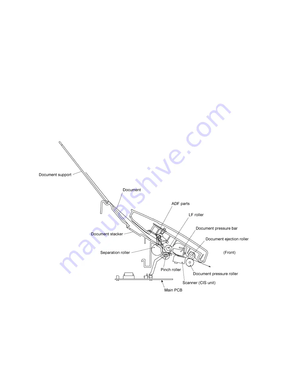
Transmitting Mechanism (Feeding and scanning documents)
The transmitting mechanism consists of the document stacker, automatic document feeder (ADF),
document feeding related rollers, scanner, and document sensors. (For details about the sensors,
refer to Section 2.4.)
For the drive power source, refer to Section 2.3.
2.1.1
Automatic document feeder (ADF)
If the operator sets documents on the stacker and starts the transmitting operation, the ADF
(consisting of the separation roller and ADF parts) feeds those documents into the equipment,
starting from the bottom sheet to the top, page by page. Each document advances to the scanner
with the LF roller, and then it is fed with the document ejection roller.
Summary of Contents for FAX 750
Page 4: ...CHAPTER I GENERAL DESCRIPTION ...
Page 11: ...CHAPTER II INSTALLATION ...
Page 12: ...CHAPTER III THEORY OF OPERATION ...
Page 14: ...III 1 1 OVERVIEW Not provided on the FAX 910 ...
Page 24: ...III 11 Active Gears on the Inner Side of the Drive Unit ...
Page 26: ...III 13 Active Gears on the Inner Side of the Drive Unit ...
Page 30: ...III 17 Location of Sensors and Actuators 1 ...
Page 31: ...III 18 Not provided on the FAX 910 Location of Sensors and Actuators 2 ...
Page 34: ...III 21 FAX750 FAX770 FAX 910 FAX 920 FAX 921 MFC 925 FAX870MC FAX 930 FAX 931 MFC970MC ...
Page 39: ...CHAPTER IV DISASSEMBLY REASSEMBLY LUBRICATION AND ADJUSTMENT ...
Page 44: ...IV 4 n n Disassembly Order Flow ...
Page 48: ...IV 8 4 Disconnect the panel main harness ...
Page 52: ...IV 12 ...
Page 70: ...IV 30 Remove the two screws and lift up the paper feed chute ...
Page 72: ...IV 32 ...
Page 78: ...IV 38 ...
Page 86: ...IV 46 1 17 Harness Routing ...
Page 88: ...IV 48 ...
Page 89: ...IV 49 2 LF roller ASSY 3 Platen frame ASSY ...
Page 90: ...IV 50 ...
Page 91: ...IV 51 4 Separation roller and main frame ...
Page 92: ...CHAPTER V MAINTENANCE MODE ...
Page 99: ...V 6 Scanning Compensation Data List ...
Page 150: ...CHAPTER VI ERROR INDICATION AND TROUBLESHOOTING ...
Page 168: ...July 98 5X4401 Printed in Japan ...
Page 177: ......
Page 178: ......
Page 182: ......
Page 184: ......
Page 197: ......
Page 198: ......
Page 202: ......
Page 216: ......
Page 218: ......


