


VI
- 13
2.4
Troubleshooting Procedures
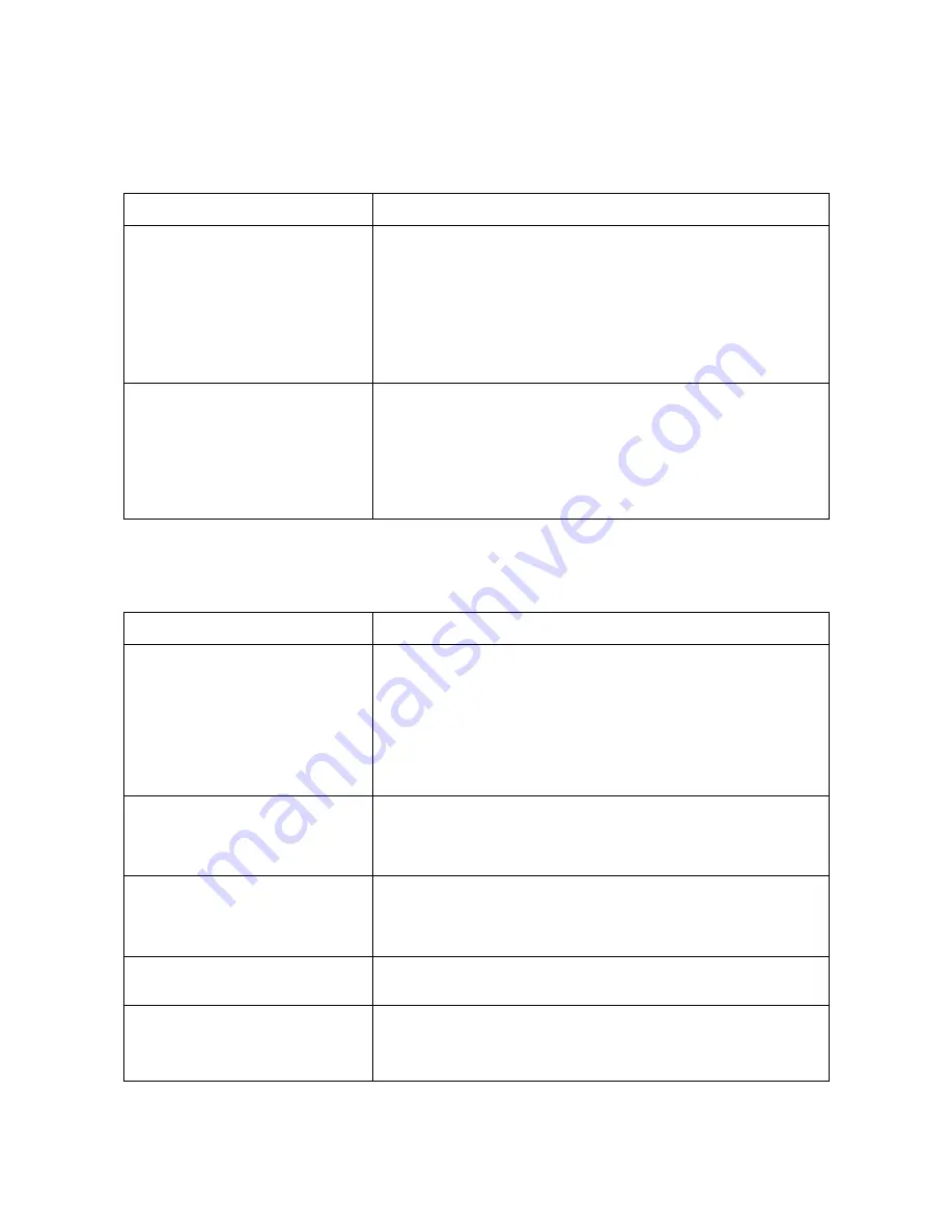
[ 1 ] Control panel related
Trouble
Check:
(1) LCD shows nothing.
• Panel-main harness between the main PCB and the control PCB
• Interfaces between the main PCB, NCU PCB and power supply
PCB
• LCD
• Control panel PCB
• Power supply PCB
• Main PCB
(2) Control panel inoperative.
• Panel-main harness between the main PCB and the control PCB
• Interfaces between the main PCB, NCU PCB and power supply
PCB
• Control panel PCB
• FPC key
• Main PCB
[ 2 ] Telephone related
Trouble
Check:
(1) No phone call can be made.
• FPC key
• Control panel PCB by using the maintenance-mode function
code 13. If any defective keys are found, replace them. (Refer
to Chapter V, Section 3.7, "Operational Check of Control Panel
PCB.")
• NCU PCB
• Main PCB
(2) Speed dialing or one-touch
dialing will not work.
• Ordinary dialing function (other than the speed and one-touch
dialing)
If it works normally, check the main PCB; if not, refer to item (1)
above.
(3) Speaker silent during on-hook
dialing.
• Ordinary dialing function (Pick up the handset and press the
numerical keys.)
If it works normally, proceed to the following checks; if not, refer
to item (1) above.
(4) Dial does not switch between
tone and pulse.
• Main PCB
(5) Telephone does not ring.
• Speaker
• NCU PCB
• Main PCB
Summary of Contents for FAX 750
Page 4: ...CHAPTER I GENERAL DESCRIPTION ...
Page 11: ...CHAPTER II INSTALLATION ...
Page 12: ...CHAPTER III THEORY OF OPERATION ...
Page 14: ...III 1 1 OVERVIEW Not provided on the FAX 910 ...
Page 24: ...III 11 Active Gears on the Inner Side of the Drive Unit ...
Page 26: ...III 13 Active Gears on the Inner Side of the Drive Unit ...
Page 30: ...III 17 Location of Sensors and Actuators 1 ...
Page 31: ...III 18 Not provided on the FAX 910 Location of Sensors and Actuators 2 ...
Page 34: ...III 21 FAX750 FAX770 FAX 910 FAX 920 FAX 921 MFC 925 FAX870MC FAX 930 FAX 931 MFC970MC ...
Page 39: ...CHAPTER IV DISASSEMBLY REASSEMBLY LUBRICATION AND ADJUSTMENT ...
Page 44: ...IV 4 n n Disassembly Order Flow ...
Page 48: ...IV 8 4 Disconnect the panel main harness ...
Page 52: ...IV 12 ...
Page 70: ...IV 30 Remove the two screws and lift up the paper feed chute ...
Page 72: ...IV 32 ...
Page 78: ...IV 38 ...
Page 86: ...IV 46 1 17 Harness Routing ...
Page 88: ...IV 48 ...
Page 89: ...IV 49 2 LF roller ASSY 3 Platen frame ASSY ...
Page 90: ...IV 50 ...
Page 91: ...IV 51 4 Separation roller and main frame ...
Page 92: ...CHAPTER V MAINTENANCE MODE ...
Page 99: ...V 6 Scanning Compensation Data List ...
Page 150: ...CHAPTER VI ERROR INDICATION AND TROUBLESHOOTING ...
Page 168: ...July 98 5X4401 Printed in Japan ...
Page 177: ......
Page 178: ......
Page 182: ......
Page 184: ......
Page 197: ......
Page 198: ......
Page 202: ......
Page 216: ......
Page 218: ......